the alternator lead when using the MVP, ease of installation should be the determining factor in this
installation. If more than one shunt is required, a second shunt can be installed through a FM-VA-M-
(50 or 300) Functional Module. The Functional Modules come with their own installation instruc-
tions.
B. B.
B. B.
B.
Install the External Shunt:Install the External Shunt:
Install the External Shunt:Install the External Shunt:
Install the External Shunt:
The external shunt should be installed in an appropriate location that
minimizes the routing of main cables (refer to figure 1 or 2 as appropriate
for your installation). It should also be mounted in a location where
inadvertent damage cannot occur. If the shunt can be accessed easily, it
should be covered. When mounting the shunt, use self-locking or safety-
wired nuts.
The signal wires from the shunt to the EDC must be fused a short distance after they leave the shunt.
If this is a new installation, install two in-line one-amp fuses, one in each of the signal lines from the
shunt to the EDC Amp Input.
Note: Note:
Note: Note:
Note: If you are replacing an existing ammeter, the shunt may already be mounted in the aircraft. If
you already have a shunt installed and know the value of the existing shunt, the MVP can be cali-
brated to that shunt.
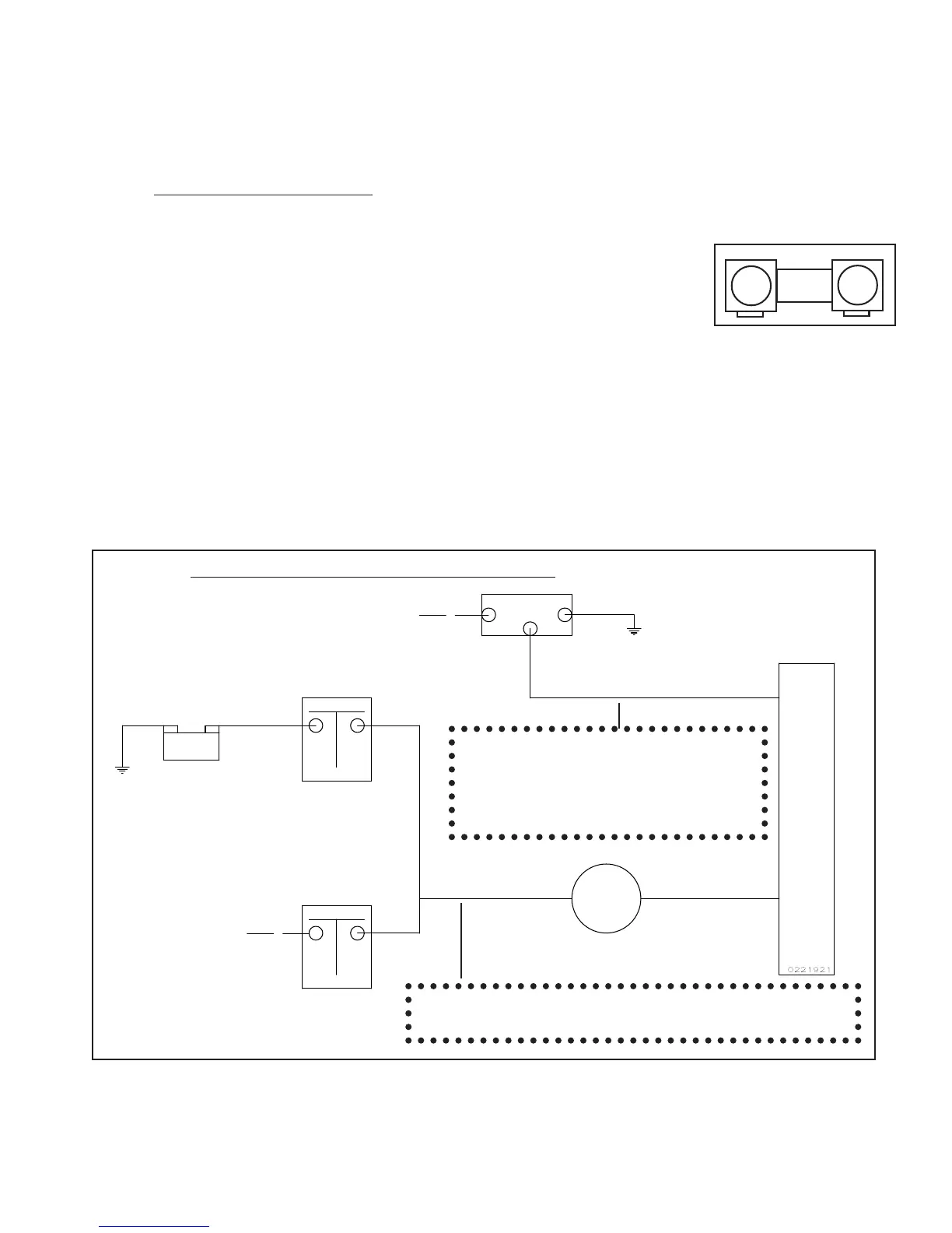
22
Shunt
Batt.
Master Switch
Contactor
Alternator
F
B
G
Starter Solenoid
External Shunt
+
-
This line may be connected currently
to the Master Switch Contactor or the
Starter Solenoid. In either case it
should be rerouted to the Bus or + side
of the Shunt.
B
U
S
This is the main lead going to the Bus. It may come from
the Master Switch Contactor or the Starter Solenoid.
To Starter
To Voltage Regulator
Figure 1: Figure 1:
Figure 1: Figure 1:
Figure 1:
External Shunt Installed in the Battery LeadExternal Shunt Installed in the Battery Lead
External Shunt Installed in the Battery LeadExternal Shunt Installed in the Battery Lead
External Shunt Installed in the Battery Lead
Note: The External ShuntNote: The External Shunt
Note: The External ShuntNote: The External Shunt
Note: The External Shunt
should not be installed in seriesshould not be installed in series
should not be installed in seriesshould not be installed in series
should not be installed in series
with the starting current.with the starting current.
with the starting current.with the starting current.
with the starting current.

 Loading...


