29
© 2009, Elektro-Automatik GmbH & Co. KG
EN
The memory sets can also be dened by remote control and
corresponding commands using a digital interface (except GPIB).
They‘re stored immediately.
The button may be locked by the condition LOCK. See below.
Pushbutton Local
This pushbutton activates or deactivate the LOCAL mode. In
LOCAL mode not remote control of the device is possible.
Attention! Activation of LOCAL mode results in immediate return
from remote control (analogue or digital) and locks the device
against further attempts to control it remotely, until LOCAL is
cleared again.
LOCAL mode is indicated by LED „Local“. As long as LOCAL is
not active, the LED „Remote“ indicates an active remote control
by analogue or digital interface.
The button may be locked by the condition LOCK. See below.
Pushbutton Lock / Unlock
This pushbutton activates or deactivates the control panel lock.
The LOCK mode locks all buttons, except the LOCK button itself,
and the rotary encoders against unintended operation.
Attention! Activation of the LOCK mode instantly exits any preset
or memory mode, if currently active. The display will return to
normal display of actual values.
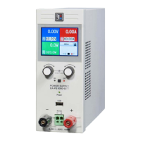
Pushbutton Output On / Output Off
This pushbutton is used to manually switch the power output on
or off, as long as the device is not in remote control mode. The
output condition is always indicated by the LEDs „Output On“ or
„Output Off“. If the output is switched on, the device indicates the
currently active regulation mode (CC, CV or CP (only models from
1kW)) in the status area in the middle of the display.
The button may be locked by the condition LOCK. See above.
Switching the output on may be inhibited by pin 13 (REM-SB) of
the analogue interface. See section „10. Analogue interface“.
The button also acknowledges the errors. See sections 7.4 and
7.5 fore more information.
Operating the device
6.3 Other control elements
Pushbuttons Rotary encoder
Both of the rotary encoders have a push button function. Pushing
any or both of these will effect following:
a) Fine adjustment mode (Fine)
A short push of any of both buttons activates or deactivates the
neadjustmentmode.If„Fine“isactive,allsetvalues,thresholds
and limits can be adjusted in smallest possible steps, no matter
what mode is currently active (preset, memory ect.). It is indicated
by the status text „Fine“ in the status area. Also see section „6.4
Adjusting set values“ below.
b) Device setup
Pushing both buttons together for >3s while the output is off
changes to device setup. It is exited the same way.
6.4 Adjusting set values
1. Manual operation
During manual operation, both rotary encoders are used to con-
tinuously adjust the set values of voltage and current from 0% to
100%nominalvalueinpredenedsteps(seetable).Inordertoset
the values for OVP and UVL the button Preset UVL/OVP has to
pushed once or twice. In order to set the power set value (models
from 1kW only) the button Preset Power has to be pushed.
Attention! The OVP value can be lower than the voltage set value
and will cause an OV error as soon as the output is switched on
and the actual voltage reaches the OVP threshold!
Setting values manually can be done in ne or coarse steps,
whereas coarse is default. Fine is required to be activated by the
one of rotary encoder pushbuttons and has a step width of 1.
For coarse adjustment, following step widths apply in dependency
of the nominal values (also refer to technical specs):
Voltage Current
Nom. value Step width Nom. value Step width
16V 0,1V 4A 50mA
32V 0,2V 5A 50mA
65V 0,5V 10A 0,1A
80V 0,5V 15A 0,1A
160V 1V 20A 0,2A
360V 2V 40A 0,5A
60A 0,5A
Power
Nom. value Step width
1000W 0.001kW
1500W 0.001kW
Important! The resolution of the set value adjustment in some
cases is, depending on the nominal values, higher than the one
of the output voltage. Thus it can happen that the output voltage
only changes every 2 or 3 steps.

 Loading...