33
© 2009, Elektro-Automatik GmbH & Co. KG
EN
• The input REM-SB (remote standby, pin 13) overrides the
pushbutton Output On. It means, the output can not be switched
onbythebuttonifthepindenestheoutputstateas„off“Soit
can be as emergency power off.
• The output VREF can be used to build set values for the set
value inputs VSEL, CSEL and PSEL. For example, if only
current control is required, pin VSEL and PSEL can be bridged
to VREF. CSEL is then either fed by an external voltage (0...5V
or 0...10V) or via a potentiometer between VREF and ground.
Also see next section.
• Putting in set values up to 10V while the 0...5V range is selected
will ignore any voltage above 5V (clipping) and keep the output
value at 100%.
• The grounds of the analogue interface are related to minus
output.
Operating the device
10.2 Example applications
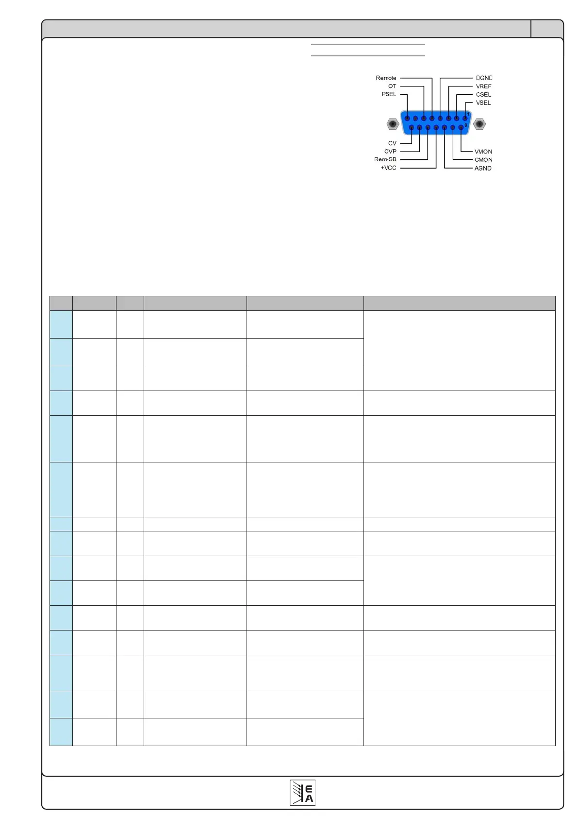
Overview D-Sub socket
Attention! Never connect grounds of the analogue
interface to minus (negative) output of an external
control application (PLC, for example), if that control
application is otherwise connected to the neative pow-
ersupplyoutput(groundloop).Loadcurrentmayow
over the control leads and damage the device!
Pin Name Type* Description Level Electricalspecication
1 VSEL AI Set value: voltage
0…10V or 0...5V correspond
to 0..100% of U
Nom
Accuracy < 0,2%
Impedance Ri >100K
2 CSEL AI Set value: current
0…10V or 0...5V correspond
to 0..100% of I
Nom
3 VREF AO Reference voltage 10V or 5V
Accuracy < 0.2% at I
Max
= +5mA
Short-circuit-proof against AGND
4 DGND POT
Reference potential for
digital control signals
For +Vcc, control and status signals
5 REMOTE DI
Toggle between internal
or external control
External = LOW, U
Low
<1V
Internal = HIGH, U
High
> 4V
Internal = open
U range = 0 …30V
I
Max
= +1mA at 5V
Sender: Open collector against DGND
6 OT DO Overtemperature error
OT = HIGH, U
High
> 4V
no OT = LOW, U
Low
<1V
Quasi open collector with pull-up to Vcc **
At 5V at the output there will be max.+1mA
I
Max
= -10mA at U
CE
= 0.3V
U
Max
= 0...30V
Short-circuit-proof against DGND
7 N.C. Not connected
8 PSEL AI Set value: power
0…10V or 0...5V correspond
to 0..100% of P
Nom
Accuracy < 0.5%
Impedance Ri >100K
9 VMON AO Actual value: voltage
0…10V or 0...5V correspond
to 0..100% of U
Nom
Accuracy < 0.2% at I
Max
= +2mA
Short-circuit-proof against AGND
10 CMON AO Actual voltage: current
0…10V or 0...5V correspond
to 0..100% of I
Nom
11 AGND POT
Reference potential for
analogue signals
For -SEL, -MON, VREF signals
12 +Vcc AO
Auxiliary voltage output
(Ref: DGND)
11...13V
I
Max
= 20mA
Short-circuit-proof against DGND
13
REM-SB DI Output off
off = LOW, U
Low
<1V
on = HIGH, U
High
> 4V
on = OPEN
U range = 0…30V
I
Max
= +1mA at 5V
Sender: Open-Collector against DGND
14 OVP DO Overvoltage error
OVP = HIGH, U
High
> 4V
no OVP = LOW, U
Low
<1V
Quasi open collector with pull-up to Vcc **
At 5V at the output there will be max.+1mA
I
Max
= -10mA at U
ce
= 0.3V
U
Max
= 0...30V
Short-circuit-proof against DGND
15 CV DO
Indication of voltage
regulation active
CV = LOW, U
Low
<1V
CC = HIGH, U
High
>4V
* AI = Analogue input, AO = Analogue output, DI = Digital input, DO = Digital output, POT = Potential
** Internal Vcc = 13.8V
 Loading...