34
© 2006, Elektro-Automatik GmbH & Co. KG
Irrtümer und Änderungen vorbehalten
EN
© 2009, Elektro-Automatik GmbH & Co. KG
Output off (emergency off)
Pin „REM-SB“ is always operative and does not depend on the
remote mode. It can thus be used to switch off the output without
extra means, for example as an emergency power off function.
All the user has to do is to ensure the level of the input is held.
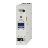
Remote control of current and voltage
Two potentiometers between VREF and ground, sliders at the
inputs VSEL and CSEL. The power supply can be controlled as
with the rotary encoders on the front and can either operate as
current or voltage source. In compliance with the max. 3mA for
the VREF output, potentiometers with at least 10kOhm have to
be used.
The power set value is here, for models with power regulation
feature, tied to VREF and thus 100%.
or
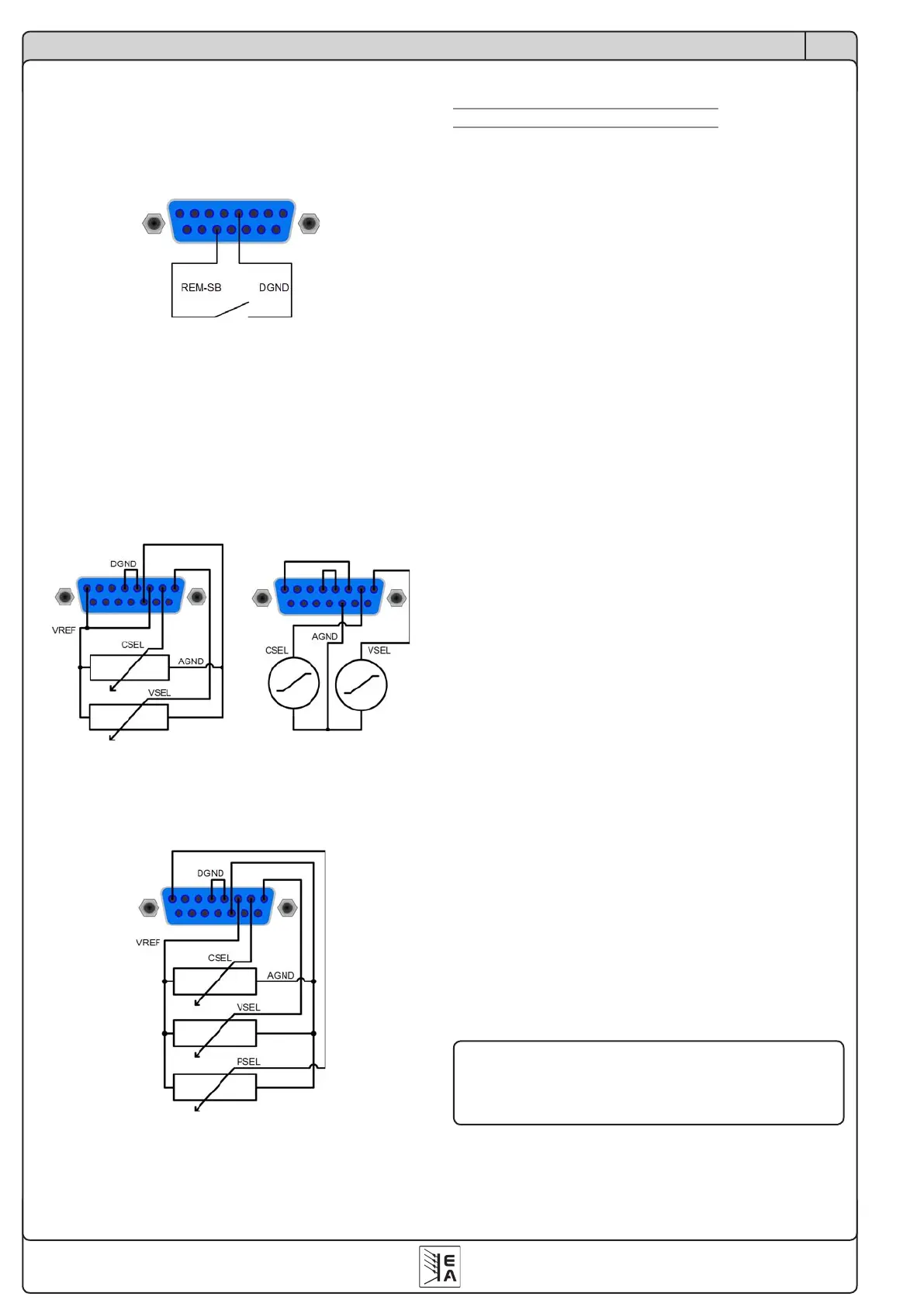
Remote control with power
Similiar to the example above, but with adjustable power limit.
Operating the device
11. Miscellaneous
11.1 Functions of terminal System Bus
The 8pole terminal System Bus is located on the rear and is used
to connect leads for remote sense or to wire multiple devices for
series or parallel connection.
Pin assignment:
1 : Sense +
2 : Sense -
3 : Master output Current
4 : Master output Voltage
5 : Slave input Current
6 : Slave input Voltage
7 : Share Bus
8 : Ground
Attention! The functions of pins 3-8, as described in the
subsequent paragraphs, are only available at models
from 1000W output power.
Following wiring schemes can be realised:
11.1.1 Series connection in Master-Slave mode
Note: not available for 160V and 720V models!
Note: only available with devices from 1kW nominal power!
For a series connection, it is recommended to use only devices
with identical output current, else the unit with the lowest nominal
outputcurrentwilldenethemaximumcurrentofthesystem.
One unit is always the master of the next unit, which becomes
slave, and so on. When connecting more than two units, it is
recommended to consider one certain unit as master and any
other as slave. The slave(s) are controlled by the master via the
slave input pins 3 and 4 of the terminal System Bus. Voltage and
current can be controlled simultaneously, but also seperately.
For an example wiring see gure 5. Voltage and current are
here given by the master. In case only one of both, voltage or
current, is going to be controlled, the other set value should be
set to 100%.
Inordertocontrolthewholesystemremotely,itissufcientto
control the master via its analogue or digital interface. When
reading actual values, the current monitor value will represent the
overall system current, but the voltage monitor only the output
voltage of the master. In order to get accurate readings, either
the actual voltage is multiplied by the number of unit in the series
connection (only applicable if all are same type) or all units will
have to be read seperately.
Attention! In case one of the output poles is going to be grounded,
it is recommended for safety reasons to ground the pole with the
lowest potential, in this case minus output (-) of the master.
Attention! The system master must always be the unit with
the lowest potential!
!
Caution! The maximum allowed 720V total
voltage of a series connection must not be
exceeded!

 Loading...