22
© 2006, Elektro-Automatik GmbH & Co. KG
Irrtümer und Änderungen vorbehalten
EN
© 2009, Elektro-Automatik GmbH & Co. KG
Table of contents
Page
1. Introduction 2
3
2. Technicalspecications 2
3
2.1 Control panel and display 2
3
2.2 Technicalspecications 2
4
3. Device description 2
5
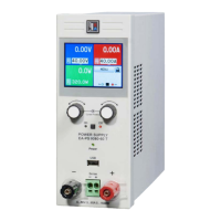
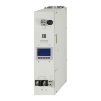
3.1 Views 2
5
3.2 Scope of delivery 2
6
4. General 2
6
4.1 Prologue / Warning 2
6
4.2 Cooling 2
6
4.3 Opening the device 2
6
5. Installation 2
6
5.1 Visual check 2
6
5.2 Mains connection 2
6
5.3 DC output terminal 2
6
5.4 Terminal „Sense“ (Remote sense) 2
6
5.5 Interface card slot 2
6
6. Handling 2
6
6.1 The display 2
6
6.2 Pushbuttons on the control panel 2
7
6.3 Other control elements 2
9
6.4 Adjusting set values 2
9
7. Behaviour of the device when... 3
0
7.1 Switching on by power switch 3
0
7.2 Switching off by power switch 3
0
7.3 Switching to remote control 3
0
7.4 Overvoltage occurs 3
0
7.5 Overtemperature occurs 3
1
7.6 Voltage, current and power are regulated 3
1
7.7 Remote sense is active 3
1
7.8 Mains undervoltage or overvoltage occurs 3
1
7.9 Connecting different types of loads 3
1
8. Device setup 3
2
9. Digital interface cards 3
2
10. Analogue interface 3
2
10.1 General 3
2
10.2 Example applications 3
3
11. Miscellaneous 3
4
11.1 Functions of terminal System Bus 3
4
11.1.1 Series connection in Master-Slave mode 3
4
11.1.2 Parallel connection in Share Bus mode 3
5
11.1.3 Parallel connection in Master-Slave mode 3
5
11.2 Networking 3
7
11.3 Accessories and options 3
7
 Loading...