31
© 2009, Elektro-Automatik GmbH & Co. KG
EN
Operating the device
7.5 Overtemperature occurs
Ambient temperatures higher than specied must be avo-
ided!
As soon as an overtemperature (OT) error occurs by internal
overheating, the output is switched off and the status text „OT“
is indicated.
Simultaneously, the LED „Output On“ willash,indicatingthatthe
output will automatically switch on again as soon as the device
has cooled down. In case this is not wanted, the output can be
manuallyswitchedoff.ThentheLEDstopsashingandtheoutput
won‘t switch automatically on.
OT errors have to be acknowledged. If the output is off after the
device has cooled down, this is done by switching the output on
using button Output on or pin „REM-SB“ or the corresponding
command. If the output is on, acknowledgement is done by
pushing the button Output on once or giving pin „REM-SB“ a
high-to-low toggle or using the corresponding command to switch
the output off.
OT errors are recorded as alarm into the internal alarm buffer.
This buffer can be read out via the digital interface.Reading the
buffer will also acknowledge.
OT error status has lower priority than OV error status. In case
an OV error occurs while an OT error is present and indicated,
the status text „OT“ will be overwritten by „OVP“.
7.6 Voltage, current and power are regulated
The output voltage of the power supply and the resistance of the
load determine the output current. If this current is lower than the
current limitation set by the current set value, then the device
is working in constant voltage (CV) regulation, indicated by the
status text „CV“.
If the output current is limited by the current set value or by the
nominal current, the device will change to constant current (CC)
regulation mode, indicated by the status text „CC“.
Models from 1kW output power additionally feature an adjustable
power limitation for 0...P
Nom
. It becomes active and overrides con-
stant voltage or constant current regulation mode, if the product
of actual current and actual voltage exceeds the adjusted power
limitation or nominal power of the device. The power limitation
primarily affects the output voltage. Because voltage, current and
power limitation affect each other, various situations like these
may occur:
Example 1: the device is in constant voltage regulation, then the
power is limited down. As a result, the output voltage is decreased.
A lower output voltage results in a lower output current. In case
the resistance of the load is then decreased, the output current
will rise again and the output voltage will sink further.
Example 2: the device is in constant current regulation, the output
voltageisdenedbytheresistanceoftheload.Thenthepower
is limited down. Output voltage and current are decreasing to
values according to the formula P = U * I. If the current set value
is then decreased, the output current would also decrease and
thus the output voltage. The product of both values, the actual
power, would sink below the previously set power limit and the
device would change from constant power regulation (CP) to
constant current regulation (CC).
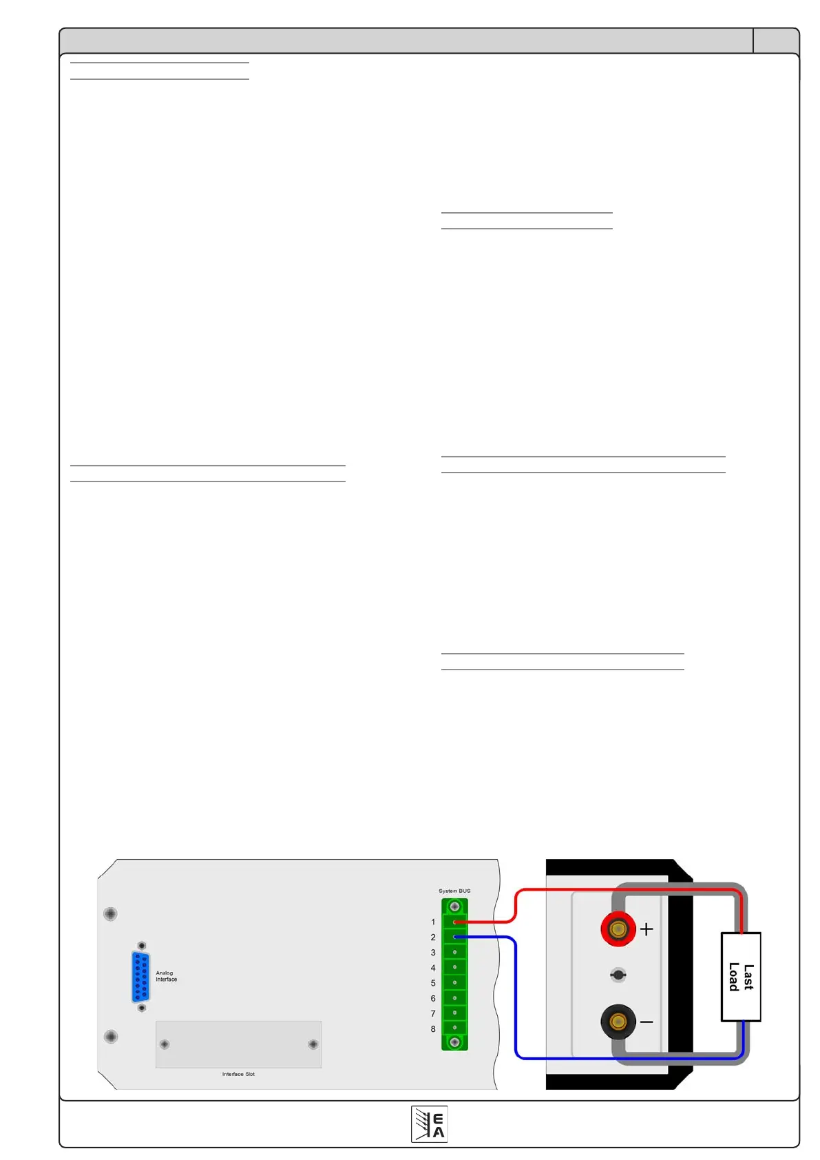
7.7 Remote sense is active
Remote sense operation is used to compensate voltage drops
along the leads between the power supply and the load. Because
this is limited to a certain level, it is recommended to match the
cross section of the load leads to the output current and thus
minimise the voltage drop.
The sense input is located on the rear, at terminal System Bus,
where the sense leads are connected to the load with correct pola-
rity. The power supply will detect the external sense automatically
and compensate the output voltage by the actual voltage at the
load instead of the output. The output voltage will be raised by the
value of the voltage drop between power supply and load.
Maximum compensation: 1V per lead.
Alsoseegure4below.
7.8 Mains undervoltage or overvoltage occurs
ThedevicefeaturesanactiverecticationwithPFCandawide
range input. This means, it can be operated at input voltages of
approx. 90V...264V. Input voltages below 90V are considered as
blackout, respectively as complete switch-off and will store the
last condition, as well as switch off the power output.
Permanent input undervoltage or overvoltage must be
avoided!
Important! Models with 1500W nominal power will derate
the output power down to 1000W at input voltages below
approx.150V.
7.9 Connecting different types of loads
Different types of loads, such as ohmic loads (lamp, resistor),
electronic loads or inductive loads (motor) behave differently and
can retroact to the power supply. For example, motors can induce
a countervoltage which may cause the overvoltage protection of
the power supply to shut off the output.
Electronic loads have regulator circuits for voltage, current and
power that can counteract to the ones of the power supply and
may result in increased output ripple or other, unwanted side ef-
fects. Ohmic loads are almost 100% neutral. It is recommended
to consider the load situation when planning applications.
Figure 4. Wiring the sense

 Loading...