35
© 2009, Elektro-Automatik GmbH & Co. KG
EN
Operating the device
11.1.2 Parallel connection in Share Bus mode
Note: this operation mode suits best for constant voltage ope-
ration.
Note: only available with devices from 1kW nominal power!
Attention! Only units of the same type (voltage and current)
must be used for this operation mode.
In order to increase the output current, two or more units of the
same type can be connected in parallel. Always take care for a
sufcientcrosssectionoftheloadleads!Preferrably,allleadsto
the load should be of same length and cross section.
Follwing connections are required: connect all (+) DC outputs of
the units to each other and all (–) DC outputs to each other. Pin
7 (Share Bus) and pin 8 (Ground) of terminal System Bus of
all units are also connected in parallel. In case remote sense is
also required, all Sense+ and all Sense - inputs are connected
in parallel and also with the load.
It is recommended to dene one unit as master that controls
voltage and current of the system. At any slave the set values of
voltage, current and power (if available) should be set to 100%.
All units displays their actual values, there will be no totals for-
mation of the system output current.
Figure 5. Series connection in Master-Slave
Inordertocontrolthewholesystemremotely,itissufcientto
control the master via its analogue or digital interface. When
reading actual values, the voltage monitor value will represent
the overall system voltage, but the current monitor only the output
current of the master. In order to get accurate readings, either the
actual current is multiplied by the number of units in the parallel
connection (only applicable if all have the same nominal output
current) or all units will have to be read seperately.
For an example wiring see gure6.
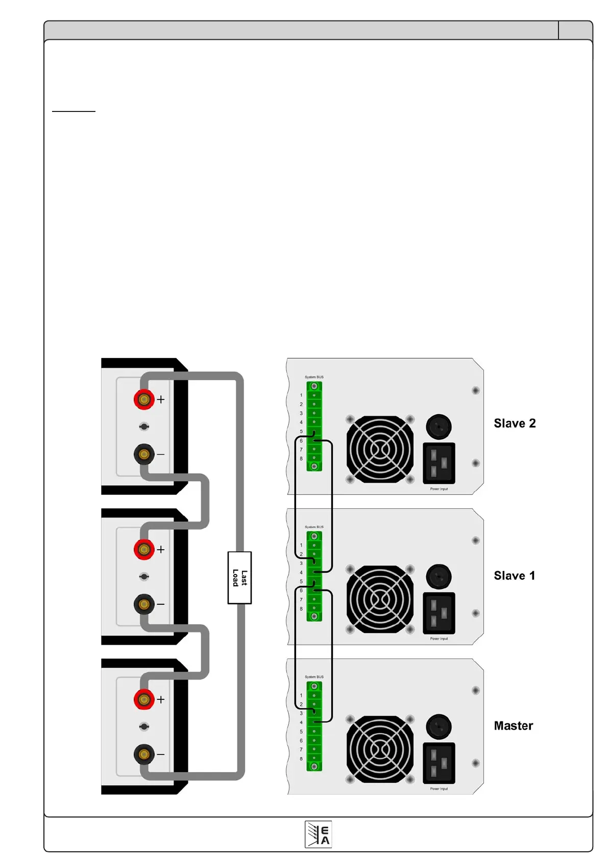
11.1.3 Parallel connection in Master-Slave mode
Note: not available for 160V and 720V models!
Note: only available with devices from 1kW nominal power!
It is possible to operate the parallel connection in Master-Slave
mode, but there are disadvantages compared to Share Bus
mode. The whole system reacts much slower, since it is not fully
analogue.
In case there is necessity to use this mode, the wiring on the
SystemBusterminalisdoneasdepictedingure5below(one
unitisalwaysthemasterofthenextunit)oroneunitisdened
as master and the master outputs of the System Bus terminal are
wired to the slave inputs of any slave (not depicted here).
 Loading...