7
DE
DD52R-E (GN 9053)
-
DD52R-E-RF (GN 9153)
Modelle, alle Rechte vorbehalten in Übereinstimmung mit dem Gesetz.
Bei Reproduktion der Zeichnungen, bitte immer Quellenangabe.
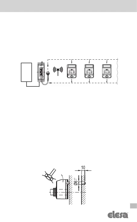
2.1 Wireless devices network
The electronic position indicators DD52R-E-RF is compatible with Elesa wireless
network which allows electronic position indicators to communicate with a PLC
via radio.
Elesa wireless network is made by the following components:
- One control unit UC-RF
- Max 36 device as DD51-E-RF, DD52R-E-RF or MPI-R10-RF
The control unit UC-RF is provided with a standard interface for the most
common industrial busses to be connected to the PLC and allows the information
transmission between the PLC and the electronic position indicators DD52R-E-RF.
The control unit UC-RF exchanges information with the electronic position indicators
DD52R-E-RF via radio frequency and allows the setting of the target position and the
control of the current position of each indicator, directly from the PLC.
WARNINGS!
Read the control unit UC-RF instructions for more details regarding its configuration.
3 Assembly
1. Drill a Ø 6x10 mm hole in the body of the machine with a 30 mm centre
distance from the shaft to fit the rear referring pin.
2. Fit the indicator onto the spindle and make sure that the referring pin fit the hole.
3. Clamp the boss to the spindle by tightening the grub screw with hexagon
socket and cup end, according to UNI 5929-85.
Current positions
PLC