FC BASIC User Manual
6/24
Remote air sensor and water sensor
Remote air sensor and water sensor:
Temperature sensor NTC, plastic cap 7x25, reinforced insulation PVC cable length=1,5m
Temperature sensor NTC, metal cap 6x40, reinforced insulationPVC cable length=1,5m
Product models selection guide:
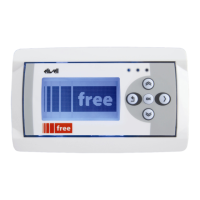
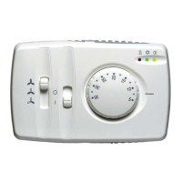
Models
210*/L
211*/L
220*/W
220*/R
221*/W
221*/R
410*/L
420*/W
420*/R
U12*/L
U22*/W
U22*/R
223*/W
U23*/W
2 pipe fan coil model ● ● ● ● ● ● ● ● ● ● ●
4 pipe fan coil model ● ● ● ● ● ● ●
Universal use model ● ● ● ●
Mode Slider Interface F1 ● ● ● ●
Interface F2 ● ● ● ● ● ● ● ● ● ●
Water sensor ● ● ● ● ● ● ● ● ● ●
Remote H/C ● ● ● ●
Manual change-over ● ● ● ● ● ● ● ●
Automatic change-over ● ● ● ● ● ●
Outputs (water valve) H or C ● ● ● ● ● ● x x x ● ●
H and C ● ● ● x x x
Electrical Resistors Electric H ● ● ● x x x ● ●
Thermo-regulator H/C ● ● ● ● Y ● ● ● ● Y ●
Dead Zone Y ● Y ● ●
Hot Start driver Timer ● ● ● ● ● ● ● ● ● ● ●
Temperature ● ● ● ● ● ● ● ●
Window contact input Frost mode ● ● ● ● ● ● ● ●
= E for models with additional ECONOMY switch on top of controller
= E for models with additional ECONOMY Function, available on terminals: clean contact or under voltage
(see electrical diagram, terminals 21-22)
x : designation of output use depends on Dip switch 1, 2 and 3 position
Y : designation of function use depends on Dip switch 3 position
PLEASE NOTE:
Water Probe mandatory for FC Basic 2 pipes model with
electrical heaters not present
electrical heaters present in integration mode
 Loading...