FC BASIC User Manual
8/24
! Is not directly affected by a heating or cooling source
! Is not mounted on an outer wall
! Is mounted on the wall at approx. 1,5 m from the floor Mounting
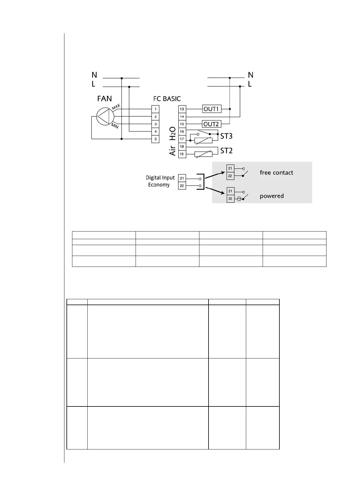
3.3 Connection diagrams
Utilities must be connected up to the FC Basic as shown below:
PLEASE NOTE: terminals 21-22 available on /N models.
Clean contact input or under voltage, depending on model (see label).
3.4 Analogue inputs
There are three analogue inputs available:
index Description sensor range meas. range
ST1 NTC sensor input. room temperature (built-in, always
available)
This is the temperature control sensor. It is always
integrated on the PCB.
The selection to use the local or remote sensor is done
through dip switch:
• DIP 6 = universal models
• DIP 4 = specific models
-->see dip switch table
-50C° 110C° -10C° 70C°
ST2 NTC sensor input. air temperature:
This is the temperature control sensor. It is always
integrated on the PCB, but can be an additional remote
sensor, positioned in the return air flow.
The selection to use the local or remote sensor is done
through dip switch:
• DIP 6 = universal models
• DIP 4 = specific models
-->see dip switch table
-50C° 110C° -10C° 70C°
ST3 NTC sensor input water temperature:
This is the sensor used to detect water temperature and
it should always be mounted downstream of the valve.
It is involved in consent and operating functions.
This input is also used for models with Remote
Heating/Cooling switch and on all other models for the
Window contact input (connection diagrams)
-50C° 110C° -10C° 70C°
PLEASE NOTE: ST2 & ST3 are NOT included in the product package.
Connections
OUTPUT
PPLICATION
2-pipe only 2-pipe with electric heater 4-pipe
OUT1
Not used Electric heater Cooling valve
OUT2
Heating/Cooling valve Heating/Cooling valve
Heating valve
 Loading...