FC BASIC User Manual
7/24
3 INSTALLATION
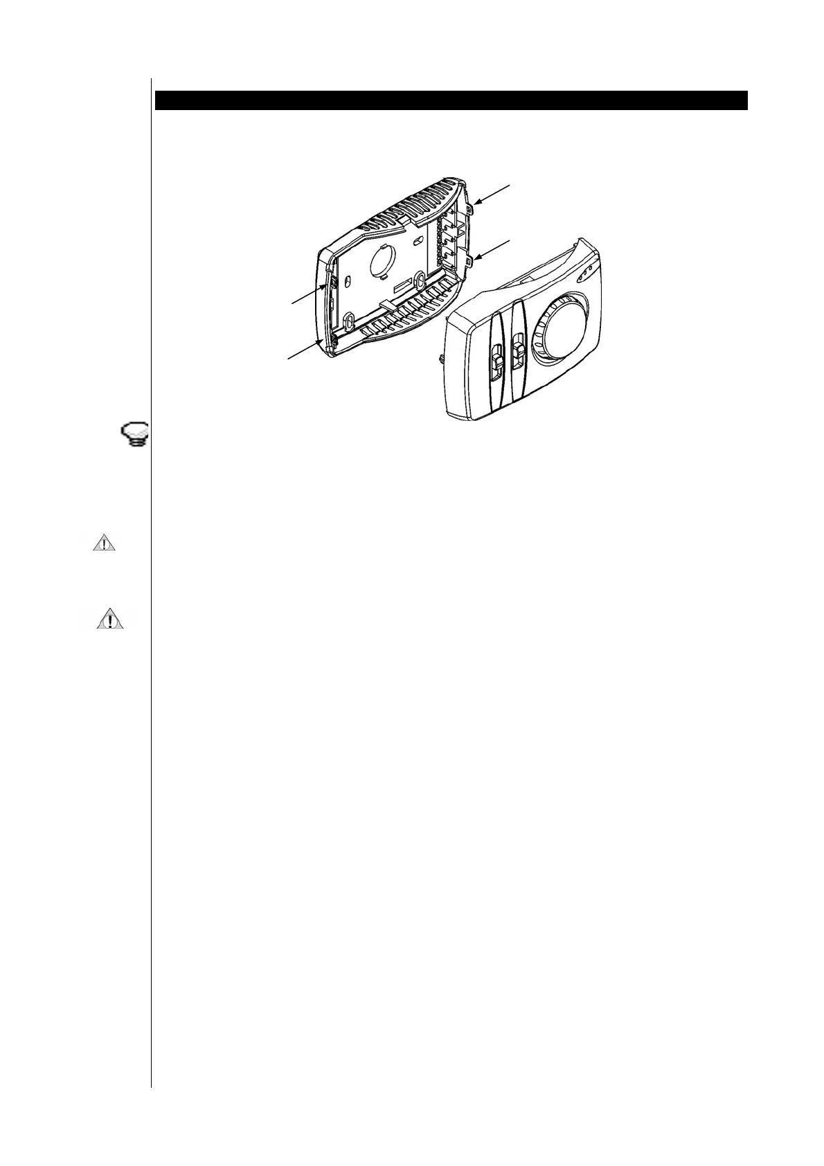
The wall-mounted version of FC Basic consists of two parts:
• the first part (connector base plate) contains connectors only, and is anchored to the wall;
• the second part (main interface) contains all electronics and controls, and can easily be fitted onto the first part.
This set-up permits easy installation with no danger of damage to electronic components.
To separate the connector base plate from the main interface, use a tiny screwdriver, insert the screwdriver into the
appropriate holes (at the side of the housing), wrest gently till both parts are separated.
FC Basic can also be installed inside the fan-coil unit. An additional remote air sensor needs to be mounted in the return
air flow on the unit.
3.1 Warnings
INSTALLATION MUST BE CARRIED OUT BY QUALIFIED PERSONNEL ONLY!
Due to the numerous functions and versions of controllers available, models offer different functions and options.
The description of the controllers in this document is general and is provided for information only.
For detailed information on the functions available, please contact an authorized dealer or the Sales Office of Eliwell.
Before installation, always read the labels fitted on the device.
Parts which are under hazardous voltage must not be accessible under regular operating conditions.
The device must be adequately protected from water and dust.
Do not install the control in environments with the following characteristics:
• Relative humidity (non-condensing) over 90%,
• Strong vibrations or shocks
• Ongoing exposure to jets of water under pressure
• Exposure to aggressive, polluting atmospheric agents which could cause corrosion or oxidation (such as sulphuric or
ammoniac substances, salt mists, fumes)
• Presence of considerable magnetic or radio interference (such as transmission antennas)
• Exposure to direct sunlight or atmospheric agents.
When connecting up controls with one another, with accessories, electric loads or other devices, take great care in relation
to the following:
• Incorrect connection with the power supply voltage could damage the control.
• Use of wire terminals which are appropriate for the terminals. Slacken the terminal screw, insert the wire terminal,
and then tighten the screw again. Check that it is tight by pulling gently on the wire. Do not use an automatic
screwing machine (or use with a torque setting of less than 50 N*cm)
• Possible electromagnetic interference: wire up low voltage utilities separately from high voltage utilities. Keep
temperature sensor cables and digital inputs separate from cables with inductive loads or power cables as much as
possible.
• Never wire power cables and temperature sensor cables through the same trunking/conduit. The remote sensor wires
must be kept far away from power devices (such as power relays). Make sure the route travelled by these cables is as
short as possible.
• Never apply loads to outputs, greater than those specified herein.
• Observe connection diagrams carefully when connecting up loads.
3.2 Mounting
The controller should be mounted in a room at a location which:
! Ensures easy access for operation
! Is free of curtains, cupboards, shelves, etc…
! Ensure free circulation of air
! Is free of direct sunlight
! Is free of draft (e.g. open window or door)
 Loading...