FC BASIC User Manual
5/24
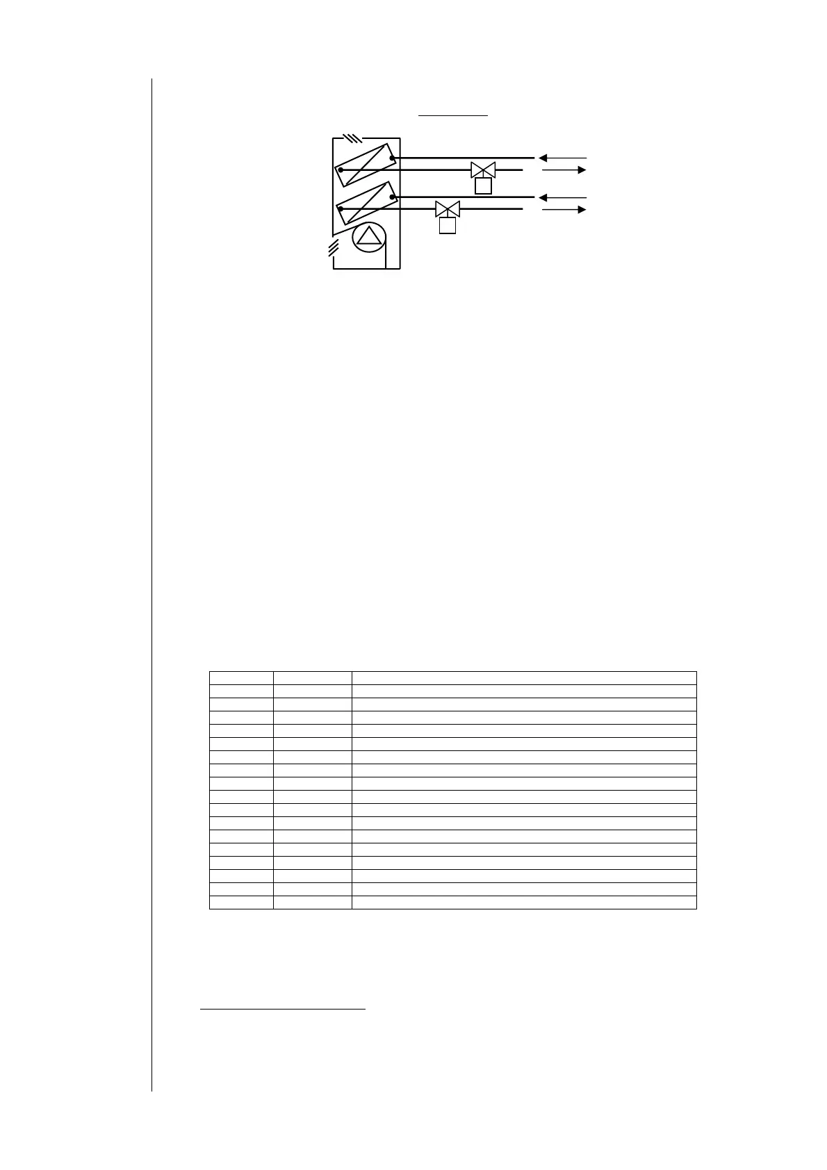
4 pipe fan-coil
DELIVERY FAN:
The fan is located just before the finned battery; and it takes back the room air via the inlet air duct.
The air flows across the batteries before being released into the room.
If the control is installed on the fan coil unit itself, an additional return air sensor, positioned in the flow of inlet air detects
the room temperature. In this case, the temperature measurement is valid only if the flow of inlet air is sufficient to nullify
or reduce stratification phenomena in the room.
WATER BATTERY – MOTORISED VALVE
Consists of a water-air exchanger, located internally, across which the inlet air travels.
Hot or cold water, produced by a boiler or a chiller, flows through the exchanger.
There may be a dual battery supply circuit (4-pipes); the 4-pipe configuration may be set up with two motorised valves and
two independent exchangers, or with a single exchanger (2-pipes). In some cases it is important to be able to measure the
temperature of the water supplied to the battery, which may be done with a water sensor located downstream of the
battery’s return and the valve.
(see Anti valve sticking)
ELECTRIC HEATERS
The electric battery may be used to heat air in 2-pipe systems when there is only cold water available (electric heaters in
regulation), or to assist heating using water when room temperature is far from setpoint (2
nd
step electric heaters in
integration).
2.2 Available models
14 versions of FC Basic are available with different operating features, summed up in the table below:
Table of models
Product code explanation:
Position Character Description
1st 2 2-pipe fan coil system only
4 4-pipe fan coil system only
U Universal model, selectable 2- or 4-pipe fan coil system (Dip switch)
2nd 1 Mode slider switch Heating/Off/Cooling (Interface F1)
2 Mode slider switch On/Off (Interface F2)
3rd 0 Electric heater not present
1 Electric heater present
2 Electric heater presence selectable (Dip switch)
3 INTEGRATED AND AUTOMATICALLY ADJUSTING electric heater
4th E Economy switch present on top of controller
N Ecnomy Function, available omn terminals
5th /L Local Heating/Cooling mode selection (local slider switch)
/R Remote Heating/Cooling mode selection (external switch)
/W Water sensor use requested
Example:
210/L : 2-pipe fan coil + H/Off/C mode slider (Interface F1) + electric heater present + local mode selection
U22E/R : Universal (2- or 4-pipe fan coil) + On/Off mode slider (Interface F2) + electric heater presence selectable +
Economy switch + remote H/C mode selection
U22N/R : Universal (2- or 4-pipe fan coil) + On/Off mode slider (Interface F2) + electric heater presence selectable +
Economy Function (available on terminals*)
+ remote H/C mode selection
*see electrical diagram, terminals 21-22
4 pipe installation
Fan control
Finned battery
Valve
Electric heaters
Hot water supply
Hot water return
Motorised valve
Cold water supply
Cold water return
Water battery
Water battery
 Loading...