RGF 300
12/53
After the motor characteristics have been checked, the following should be defined in order to identify the
type of operating mode and application.
1.3.1 Operating mode
The
rgf
controls allow two different types of operation depending on which type of input is available:
•
operation as
REGULATOR
(also called MASTER)
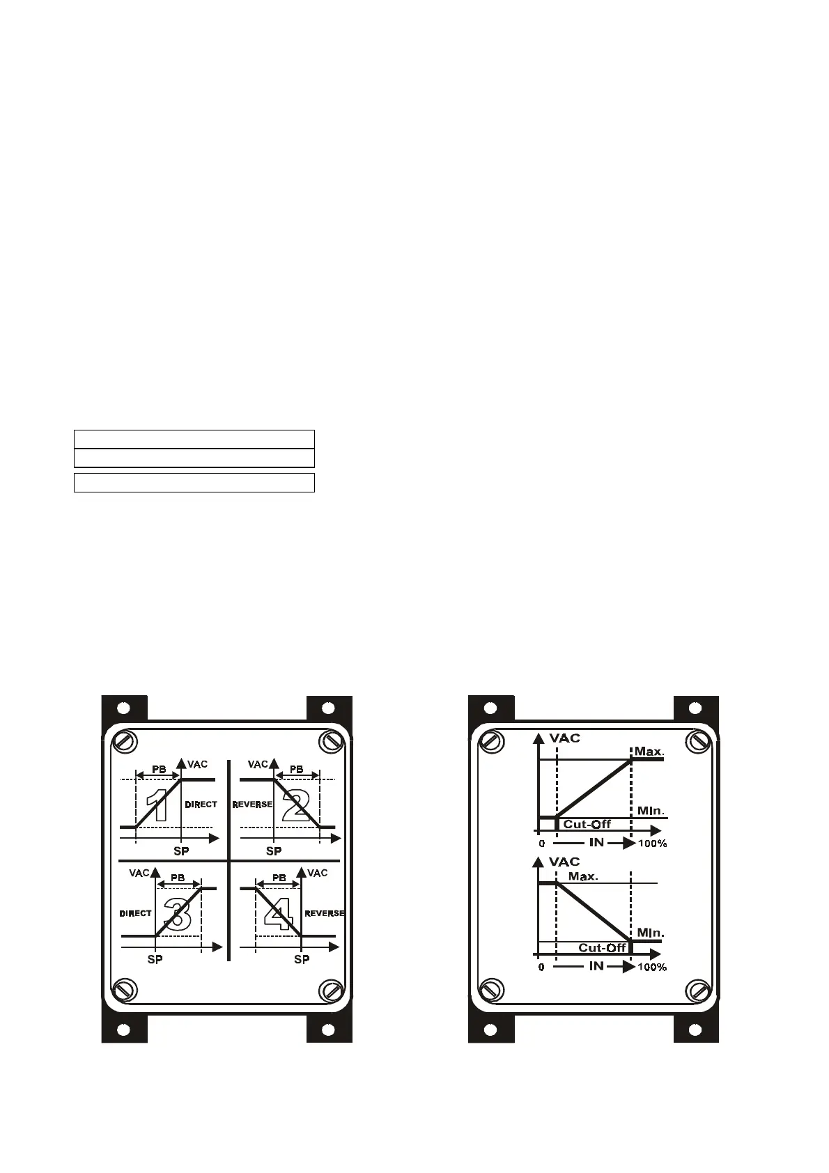
the phase cutting regulators is directly connected to one or more sensors; the phase cutting is a function of
the values selected for:
#"
Set-Point P3
(trimmer
or centesimal switch)
#"
Proportional band P2
(trimmer)
•
operation as
POWER UNIT
(also called SLAVE)
In this case, the
rgf
is set up to be controlled by an external Master regulator which decides the phase cutting
of the voltage by sending the control signal to the slave.
The incoming control signal to the
rgf300
regulators can be:
For a
MASTER (mA – Vdc)
Active sensors with control in current (
mA
) or voltage (
Vdc
)
For a
MASTER (ohm)
NTC
sensors with control in
°C/ohm ( 10 kohm @ 25 °C )
For a
SLAVE (mA – Vdc)
Control signals in current (
mA
) or voltage (
Vdc
)
1.3.2 Application
It is generally possible to connect one or two sensors/control signals to all ‘
MASTER’
and
‘SLAVE’
models; with two (
2
) sensors-signals connected, the regulator automatically selects the greater or lesser
signal.
In the case of active sensors, this can be directly powered (
24Vdc / max. 40 mA
).
The principal applications are for measuring pressure (
bar
), temperature (
°C
), humidity (
%RH
), delivery
(
cu.m/h
), superpressure (
mm.
), static pressure (
Pa
), supertemperature (
destratification
) etc. in plants and
machines.
fig. 7
MASTER SLAVE