RGF 300
35/53
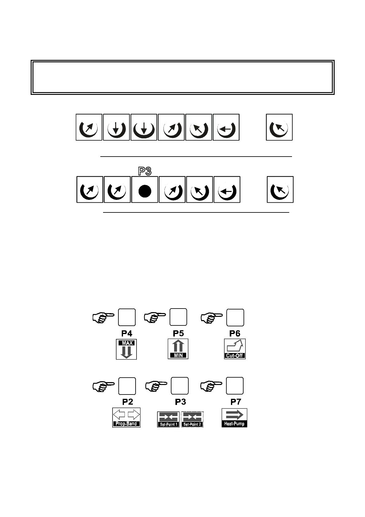
4.0 CONTROL TRIMMER
WARNING
: Before starting the regulator calibration phase, check the position of the
trimmers as shown in figs. 26 and 27.
The position of the trimmers marked with a spot of red paint (factory calibrated trimmers) must not be altered.
fig. 26
STARTING configuration for 'MASTER' regulator calibration trimmers
fig. 27
STARTING configuration for 'SLAVE' regulator calibration trimmers
The work parameters regulation can be divided into
TWO PHASES:
1.
definition of regulator work limits
: the values of
P4
and
P5/P6
are defined in this phase.
2.
definition of regulator work field
: the values of
P2
and
P3
are defined in this phase.
With
SLAVE
type regulators, the regulator calibration is completed during
PHASE 1
.
With
MASTER
type regulators,
PHASE 1
is necessarily followed by
PHASE 2
which defines the
Work
Range
and
Set-point
.
N.B.:
it is possible to read the work parameters by connecting the
HELP1
portable display unit; press the
keys as shown in
fig. 28
to display the readout of the value set with the calibration trimmers.
fig. 28
P2
P3
P4
P5
P6
P1
Mm MmMm
Mm
MmMmMm
P7
P2
P4
P5
P6
P1
Mm Mm
Mm
MmMmMm Mm
P7
%C %C%C
%C
PB
SP