RGF 300
25/53
2.3 ELECTRICAL CONNECTIONS, ON-OFF INPUTS/OUTPUT
This paragraph describes the connections to the auxiliary
S1 - S2 - S3
and
TK,
ON-OFF inputs / output
available on the ‘
MB
’ terminal board for which the electrical connection is made with
0-
POTENTIAL
signal
cables.
Also described is the operation of the
RL1 ALARM
relay and its use based on jumper
J14
.
CONNECTIONS
Trailing cable with rated cross section
1.5 sq mm / 22-14 AWG Cu
2.3.1 Operating selection
The operating selection is obtained by activating the
1/3, 2/3, 4/5
and
6/7
terminals on the '
MB
' terminal
board.
Fig. 16
shows an example of connection using switches and safety devices.
In particular:
S1
indicates a
normally open
(
NO)
switch for commutation from
AUTOMATIC
to
MANUAL
operation.
S2
indicates a
NO
contact for activation/inhibition of operation (
remote ON-OFF
);
S3
represents a
NO
contact to activate commutation from
Set-point 1
to
Set-point 2
(
SP1 – SP2
)
N.B. : this control is only operative if the RGFPB10640 optional card is present on the regulator
TK
indicates a
normally closed
(
NC
) safety device, e.g. a
HEAT PROTECTION
positioned on the motor,
which would halt operation if were open (only if
J15=ON2
).
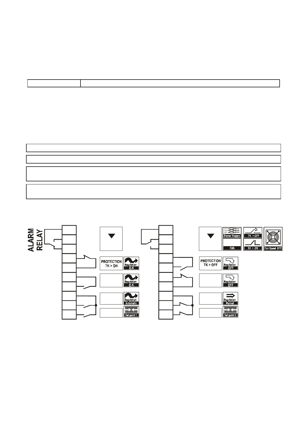
fig. 16
10
9
8
7
6
5
4
3
2
1
REMOTE
OFF
TK
S2
S1
S3
r
f
RL1
TK 2
TK 1
STOP 2
STOP 1
GND
AUT-MAN
SP1 - SP2
CONTACT
OFF
CONTACT
OFF
TK
S2
S1
S3
GENERAL
ALARM
OFF
RL1 ON
RL1
10
9
8
7
6
5
4
3
2
1
NC
NO
COM
NC
NO
COM
REMOTE
ON
CONTACT
ON
CONTACT
ON
GENERAL
ALARM
ON
RL1 ON