RGF 300
8/53
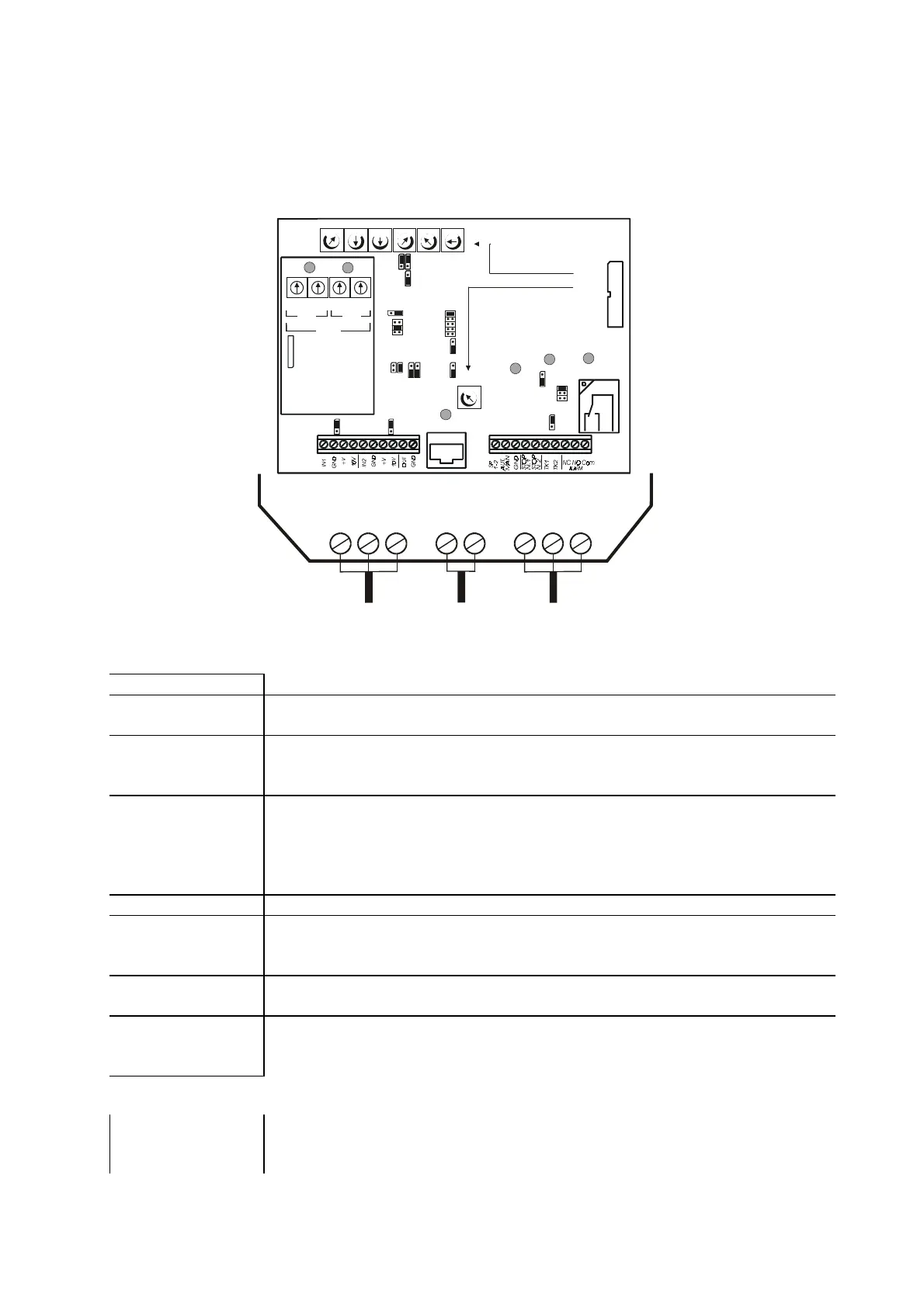
1.1 DESCRIPTION
The
rgf300
series three-phase cutting regulators comprises two electronic cards on a vetronite support
mounted inside the
GEWISS
IP55
GW Plast
120°C
case.
The two cards represent the
control
section (upper) and
power
section (lower).
fig. 4
The
control card
contains the following regulation, connection and signalling components:
•
trimmers
Marked
"
Pn
"; used to set working parameters
!"
centesimal switch
Marked “
SW
”; used for the
simply
Set-Point parameter, with
100
working points
on the transducer skale (only with
PB 1064
option)
•
relay
Marked "
RL1
"
Relay with commutation contact for external signalling of correct operation or
stop (see selection jumper
J14
).
•
Leds
AC LINE ALARM
T.K. ALARM
RL1 ON
MANUAL
Marked
"
Dln
"
RED
Led
DL1
to signal "regulator stop/fault"
RED Led DL2
to signal "external heat protection (
T.K
)."
GREEN Led DL3
to signal commutation relay
RL1
in the
N.O.
position
YELLOW Led DL4
to signal
“
HEAT PUMP
”
mode
•
jumpers
Marked
'Jn'
; used to change preset operational modes
•
flat cable
Marked
'FL'
The flat allows connection to the control and power cards.
Check the flat is securely fixed during maintenance or commissioning.
•
CN2
Rapid connector to the portable
HELP
I
10
unit for display of the
rgf300
's work
parameters
•
Inputs/output
signals terminal
boards
Terminal board MA
for connection of the control analogue input signals
Terminal board MB
for connection of the ON-OFF inputs and outputs
The
power card
contains the following connection components:
•
power supply
terminal boards
'M1'
for three-phase input supply
R,S,T
'M2'
for three-phase output
U, V, W
‘M3’
for the
Earth / PE
connection
1 2
P7
RL1
J1
P1
P2 Proportional Band
P3 Set-Point
P4
P5
P6
P7
= soft-start
=
=
= max. output
= min. output
= cut-off
= Set- H.P. mode
J2
J3
J4
J5
J6
J7
J12
J8 J10
J9
J11
J17
J5
J16
J13
J15
J14
1
2
3
1
2
3
5
4
1
2
1
2
1
2
1
2
1
2
1
2
1
2
1
2
3
1
2
1
2
1
2
P2
P3
P4
P5
P6
P1
Mm MmMm
Mm
MmMm
Mm
CN 2
FL
M2 M3 M1
MA
ALARM
AC LINE
ALARM
T.K .
RL1
ON
MANUAL
MB
SP1
RGFPB10640
(OPTIONAL)
1
2
3
4
5
6
7
8
9
0
1
2
3
4
5
6
7
8
9
0
1
2
3
4
5
6
7
8
9
0
1
2
3
4
5
6
7
8
9
0
CN3
SW1 SW2 SW3 SW4
SP1
SP2
P3
SP2