RGF 300
9/53
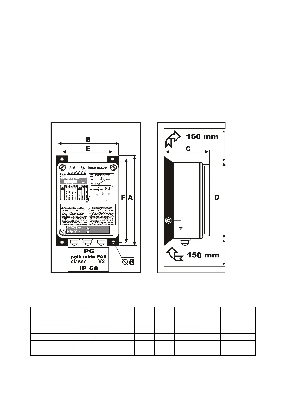
1.2 INSTALLATION AND MECHANICAL DIMENSIONS
The
rgf300
regulator must always be securely assembled and fixed using the four (
4
) attachment screws on
the side fins before connecting to the power supply.
The holes provided on the lower part of the regulator are for entry of the electric connection cables:
•
four pole line (
three phase + Earth
) to power the regulator,
•
four pole line (
three phase + Earth
) to power the load,
•
signal cable lines for the analogue inputs and digital outputs.
To make installation simpler, all regulators are also fitted with stuffing boxes in
PA6
polyamide, class
V2
,
IP68
, for use with the power and signal cables.
The regulator is cooled by natural convection and so air must be able to pass freely below and above the
appliance.
Therefore ensure there is at least
150 mm.
of free space above and below the regulator.
fig. 5
Mechanical Dimensions
MODELS A B C D E F kg.
∅
∅∅
∅
Fixing
screw holes
rgf 312
286 201 130 255 181 255 4.0
∅ 6
rgf 320
351 237 181 317 185 320 5.5
∅ 6
rgf 325
351 237 201 317 172 320 8.0
∅ 6
rgf 340
416 318 178 397 275 385 11.0
∅ 6
rgf 360
460 318 228 397 260 410 17.0
∅ 8
RL1
ON
T. K.
ALARM
AC LINE
ALARM
HELPi U NIT Heat - Pu mp