RGF 300
24/53
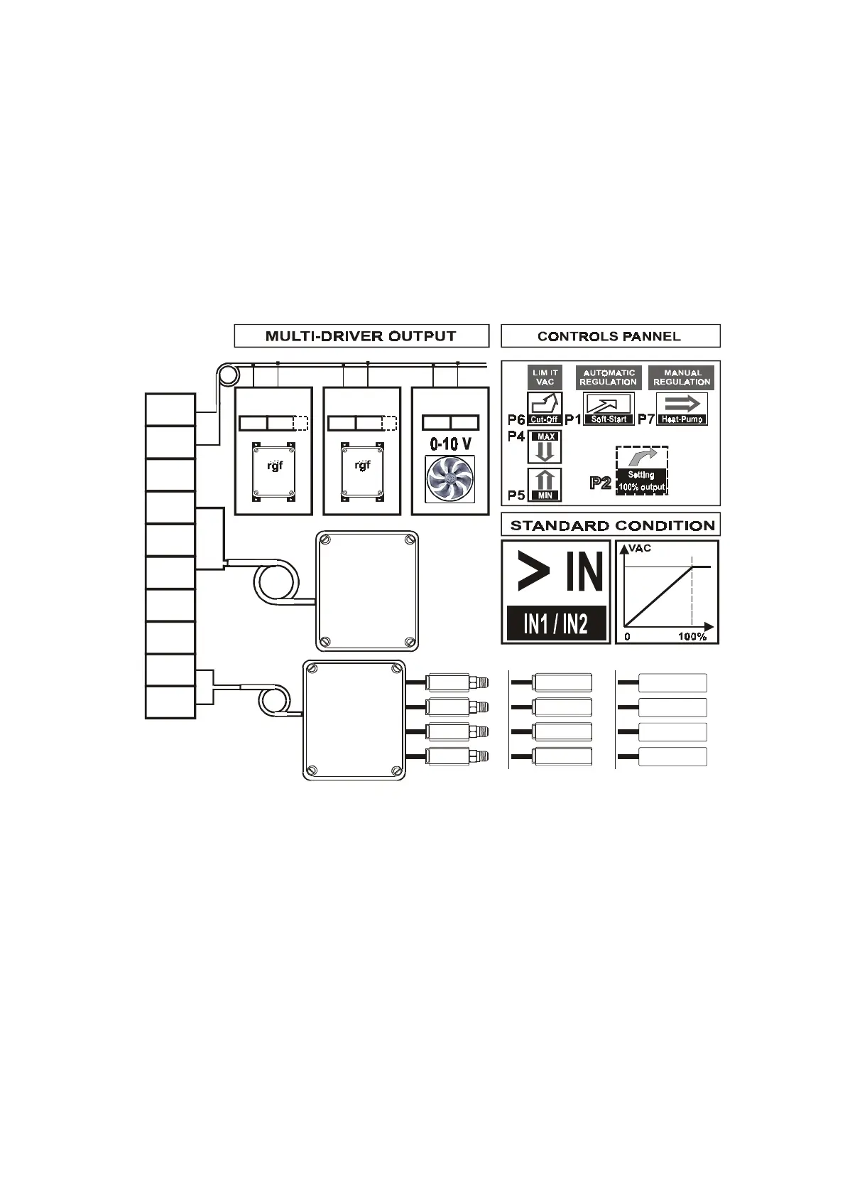
2.2.5 Connection of the rgf MULTIDRIVER control
In this configuration, the
rgf300
regulator is able to guide other single or three phase
rgf
regulators through
the
MA 9 (OUT)
and
MA 10 (GND)
terminals.
The control output controlled by jumper
J6
allows a signal to be sent to several
SLAVE
(M or V) units.
The signal takes account of the work settings on the main
rgf300
.
Using a single control / sensor, it is therefore possible to control several single or three phase regulation
units, that act both simultaneously and proportionally, starting from the transmitted regulation control
signals.
Each unit can be used singly with other work limits (
MIN
and
MAX
OUTPUT
).
The electrical connection and controls available are shown in
fig. 15
.
fig. 15
Connection of the
rgfMEI
expansion module is also shown in
fig. 15
.
With this module it is also possible to increase the number of sensors (max.
16
), which either use current (
0-
20mA
), voltage (
0-10Vdc
) or kohm (
NTC sensor
), that can be connected to the regulator.
Four sensors can be connected to this module; the control signal automatically selected is the one with the
greatest value
and as this module is supplied separately.
For more information, consult the user manual for regulator
rgfMEI
.
10
9
8
7
6
5
4
3
2
1
1 2
IN1 GND
1 2
IN1 GND
1 2
IN1 GND
300
100
GND
OUT
10V
+V
GND
IN 2
10V
+V
GND
IN 1
mA
Vdc
NTC
MEI
NTC
NTC
NTC
NTC
mA - Vdc
mA - Vdc
mA - Vdc
mA - Vdc
mA
Vdc
NTC
MEI