RGF 300
28/53
3.0 COMMISSIONING PROCEDURE
Having carried out the electrical connections to the regulator, it is time to perform the configuration,
regulation and commissioning operations for the
rgf300
regulator by following the procedure below.
It is important to remember that the settings of the
jumpers
(
Jn
) are only to be modified to change the
configuration or the operating mode of the regulator set in the factory (check the label on the right side of the
casing).
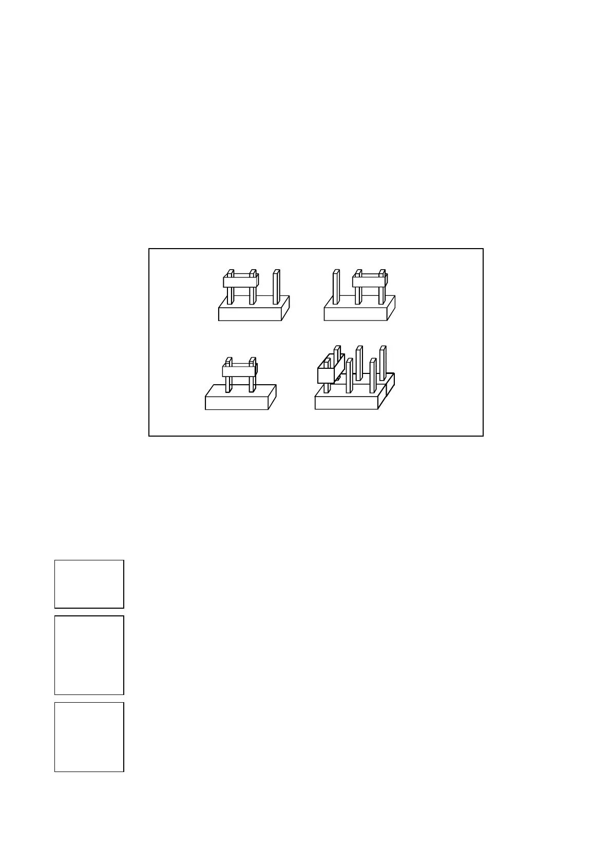
3.1 Jumpers
This paragraph describes the preset functions of the programming
jumpers
; the jumpers used on the card are
of the following types -
2, 3, 6
and
10 contacts
(see
fig. 18
).
The term "
Jumper
" refers to the moveable element which connects two (2) contacts.
fig. 18
For
2
contact jumpers, the function is activated when the
jumper
is present (position
ON
).
For
3
contact jumpers, there are two selection types:
•
position ‘
1
’ i.e. the middle jumper connected to jumper no.
1
•
position ‘
2
’ i.e. the middle jumper connected to jumper no.
2
For
6
contact jumpers (
J5
and
J14
), there are
3
selection types (pos.
1, 2, 3
);
fig. 18
shows position
1
.
For
10
contact jumpers (
J6
), there are
5
selection types (pos.
1, 2, 3, 4, 5
).
The main jumpers on the
rgf300
cutting regulators
control card
are described below.
J1
J1 = ON1
J1 = ON2
Selects the work field of the
Set-point
P3
:
P3
with control from active sensors for
4-20mA
or
NTC
(
ohm
) sensors for
°C
P3
with control from active sensors for
0-10 Vdc
J2
J2 = ON1
J2 = ON2
Activates the standard
Set-point
or the auxiliary, optional, double digital
Set-point
:
(
this control is only operative if the RGFPB10640 card is present on the regulator)
Set-point
(
P3
), with trimmer mounted on the
PB 1018/3
basic regulation card
Set-point
(
P3
), with double digital commutators in 99 positions, mounted on the
RGFPB10640;
it also inhibits operation of
P3
(standing) when in the
SLAVE
configuration,
J2 = ON2
J3
J3 = ON1
J3 = ON2
Selects the operation of the regulator at the
Set-point
:
Set-point
(
P3
) corresponds to the minimum control value of the fan
Il
Set-point
(
P3
) corresponds to the maximum control value of the fan
The standard position is
ON2.
1 2 1 2 3
1 2 1 2
3 contatti
pos.
pos.
pos.
pos.
3 contatti
1
2
1
2 contatti
6 contatti
ON
3 contacts
2 contacts
3 contacts
6 contacts