RGF 300
27/53
RL1: ALARM relay (MB 8-9-10 terminals) with J14 selection jumper
The
RL1
relay is mounted on the
control card
. The relay has a commutation contact for external signalling
of the operating status.
For the operation mode of this output relay, configure jumper
J14
so that all alarms are enabled, as shown in
the table below:
J14 RL1
POWER SUPPLY
R S T
T.K.
STOP
(S2)
FAN SPEED
U V W
RGF
ON ON ON Unable Unable O.K.
ON1
OFF OFF OFF Unable Unable K.O.
ON ON ON OFF Unable O.K.
ON2
OFF OFF OFF ON Unable K.O.
ON ON ON OFF ON O.K.
ON3
OFF OFF OFF ON OFF K.O.
Table 6
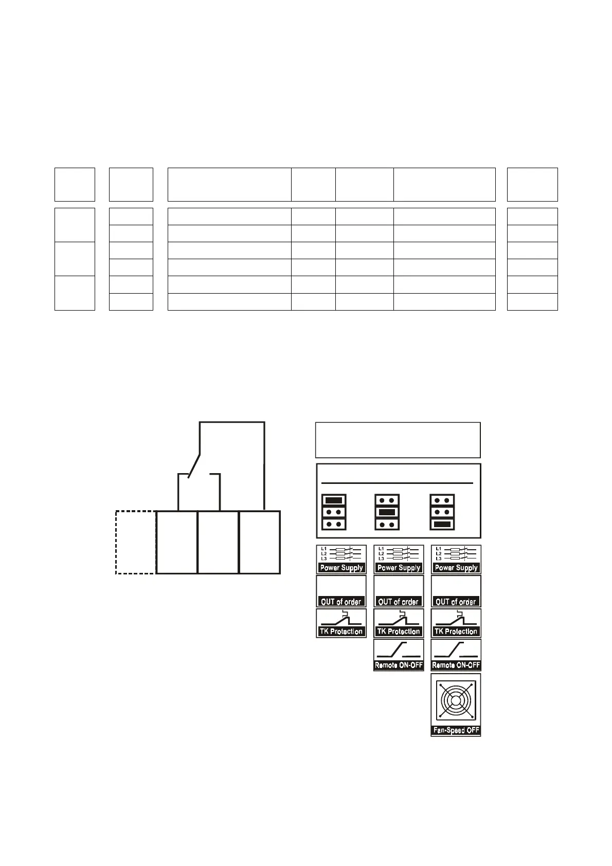
Besides relay RL1 in rest conditions,
fig. 17
shows the three positions for:
J 14
:
ON1
(
standard =
factory selection
)
.
ON2
ON3
fig. 17
10
9
8
RL1
OFF
ALARM - RELAY
NC NA Com
ON 1 ON 2 ON 3
rgf
ON 2
ON 1
ON 3
ON 2
ON 1
ON 3
ON 2
ON 1
ON 3
rgfrgf
GENERAL ALARMS
SELECTIONS