RGF 300
34/53
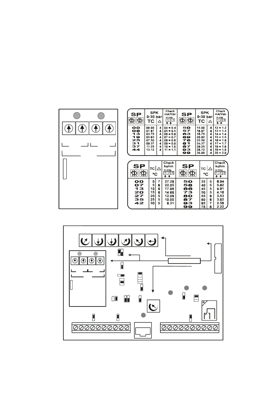
3.7 Optional module for dual Set-point configuration (SP1 – SP2)
The
rgf300
regulator can be used in versions
MASTER M, V, X, Y
with a
reference dual Set-point
by
using the
optional
module card
RGFPB10640
for double control Set-points.
Insert the card in the
CN3
connector on the
rgf300
regulator (see the position in
fig. 25
).
When the card is positioned, with
J2=ON2
, Trimmer
P3
is disabled (
standing
) and substituted by two pairs
99
position
digital commutators
.
Activating the contact on terminal board
MB 1/ 3
, it is possible to change the regulator's work point. The
commutation is shown by the lighting up of the
SP1
and
SP2 Leds
on the card above the centesimal
commutator for setting of the Set-points.
Fig. 26
shows the
RGFPB10640
card and the reference table for inputs in:
mA
(
bar/°C
for pressure transducers) and
°C
(for
NTC
sensors) in the different work ranges.
fig. 24
fig. 25
1
2
3
4
5
6
7
8
9
0
1
2
3
4
5
6
7
8
9
0
1
2
3
4
5
6
7
8
9
0
1
2
3
4
5
6
7
8
9
0
1 2
1
2
1
2
1
2
1
2
1
2
1
2
1
2
1
2
1
2
3
4
5
1
2
3
1
2
3
J1
1
2
P1 = Soft-Start
P2 = Proportional Band
P3 = (standing for J2=2)
P4 = max. output
P5 = min. output
P6 = Cut-off
P3 = Dual Set-point
P7 = MANUAL (mode H.P.)
1
2
MmmMmMmMmMmM
Mm
J2
J3
J4
J5
J6
J7
J8
J9
1
2
J10
J12J11
J17J16
J13
J14
J15
AC LINE
ALARM
T.K.
ALARM
RL 1
ON
HEAT
PUMP
P1 P2 P3 P4 P5 P6
P7
1 2 3 4 5 6 7 8 9 10
1 2 3 4 5 6 7 8 9 10
CN2
RL1
FL
PB10640
(optional)
P3
SP1 SP2
SW1 SW2 SW3 SW4
SP1 SP2
CN3
MA MB
SP1
RGFPB10640
(OPTIONAL)
1
2
3
4
5
6
7
8
9
0
1
2
3
4
5
6
7
8
9
0
1
2
3
4
5
6
7
8
9
0
1
2
3
4
5
6
7
8
9
0
CN3
SW1 SW2 SW3 SW4
SP1
SP2
P3
SP2