RGF 300
14/53
1.5 rgf
300 TECHNICAL C
HARACTERISTICS
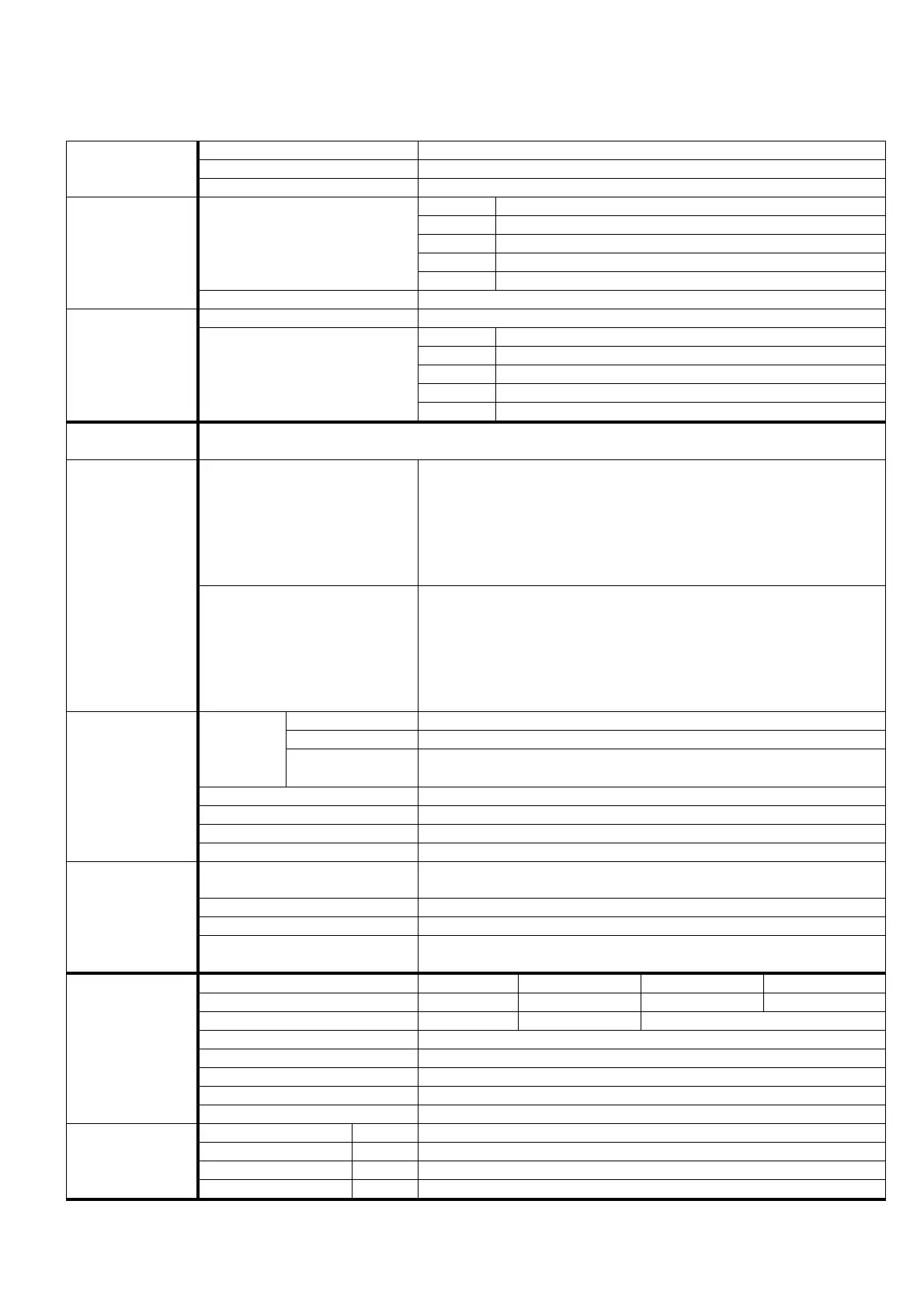
Voltage
420V
AC
+/- 10 %
three-phase (
230V
AC
and
500V
AC
on request)
Frequency
50 Hz
(
60 Hz
)
S
UPPLY
Overvoltage protection for installation Category
II
(
4 KV
)
RGF 312
12 A
up to
50°C
environment, over decrease by
0.6 A/°C
RGF 320
20 A
up to
50°C
environment, over decrease by
1.0 A/°C
RGF 325
25 A
up to
50°C
environment, over decrease by
1.2 A/°C
RGF 340
40 A
up to
50°C
environment, over decrease by
1.8 A/°C
Rated
RGF 360
60 A
up to
50°C
environment, over decrease by
2.5 A/°C
C
URRENT
Overload
200%
of the rated current (max.
10”
every
3’
)
Control circuits
10VA
RGF 312 72 W @ 12A
RGF 320 120 W @ 20A
RGF 325 150 W @ 20A
RGF 340 240 W @ 40A
P
OWER
Thermally dissipated
RGF 360 360 W @ 60A
O
PERATING
PRINCIPLE
Totally controlled three-phase cutting, with compensation for inductive loads and motors, without need for
connection to NEUTRAL
POWER unit
(Vers.
M , V
)
The output voltage depends on the control signal prevailing between the
two available at the inputs, which is chosen by means of the pre-
established mode, according to the specific appliance regulating curve.
The action can be :
DIRECT
, with the output increasing as the input increases, or
REVERSE
,
with the output decreasing as the input increases.
Standard Config.
: output increasing as the controlled variable increases
O
PERATING
CHARACTERISTIC
Regulator
(Vers.
M , V , X , Y
)
The output voltage changes to keep set to the target point, selected with
the Set-Point, the quantity measured by the transducer prevailing
between the two available at the inputs, which is chosen by means of the
pre-established mode (greater or lesser in value).
The action mode, either
direct
or
reverse,
is chosen in consideration of
the controlled quantity, transducer characteristic and load action.
Standard
: output increasing as the controlled variable increases
Vers.
M
Two
0-20 mA, Ri = 100 hom
analog inputs, priority to the greater std.
Vers.
V
Two
0-10 Vdc, Ri = 10 khom
analog inputs, priority to the greater std.
Control
Vers.
X, Y
Two
kohm
analog inputs for the
NTC
sensors supplied (
10KΩ
ΩΩ
Ω @
25°C)
, priority to the hottest sensor std.
Heat protection
O
N
/O
FF
input, motor protection NC thermal contact
Start/Stop
O
N
/O
FF
input
:
Off Vin=0 =
Start /
O
N
(
V
IN
=24V
) : Stop
Automatic/Manual
O
N
/O
FF
input
:
Off (Vin=0) =
Automatic /
O
N
(
V
IN
=24V
)=Manual
I
NPUT
SIGNALS
Set-Point 1 / Set-Point 2
O
N
/O
FF
input for Set-point 1/2 commutation (Only with
PB1064
)
Transducer supply
Two
+22Vdc (-10% / +20%) 40 mA
non-stabilised outputs, protected
from short circuit
Potentiometer supply Two
+10Vdc / 5 mA
stabilized outputs
Auxiliary control
0-10V / 1 mA
analog output for cascade control of other
SLAVE
units
O
UTPUT SIGNALS
RL1
service relay
NO/NC
relay contact, free from potential, for separate or joint signalling
of :
alarm signals absent / start enabling / voltage supply
Version & Input M: 0-20 mA V: 0-10 Vdc X: +10/+60°C Y: -20/+20°C
Target value
0 ... 20 mA 0 … 10 Vdc +10 ... +60 °C -20 ... +20 °C
Proportional range
0.4 … 4 mA 0.3 … 3.5 Vdc 3 … 30 °C
Minimum limit / Cut-Off Adjustable from
0%
to
100%
Maximum limit Adjustable from
100%
to
0%
Acceleration ramp Adjustable from
1”
to
10”
Direct/Reverse presetting Action mode of input prevailing over output :
Direct or Reverse
A
DJUSTMENTS
AND
P
RESETTINGS
Prevailing input presetting Selection mode for prevailing input :
greater
/
smaller
AC L
INE
A
LARM
ON Red
Signals locked state due to absence of one supply phase
T.K. A
LARM
ON Red
Signals locked state due to motor thermal protection
NC
contact opening
RL1 ON Green
Signals
RL1
service relay energised state
LED
SIGNALLING
M
ANUAL
M
ODE
ON Yellow
Signals “
M
ANUAL
” operation state at fixed speed