RGF 300
40/53
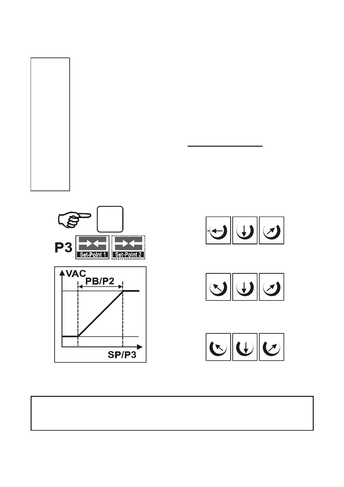
4.5 SET-POINT regulation (models M, V, X, Y) P3 trimmer - PHASE 2
P3
SET POINT
- mA
- Vdc
- °C
It is possible to activate the
SET-POINT
(the automatic regulation start point) by activating the
P3
trimmer.
In the standard configuration, the Set-Point coincides with the maximum value of supply (100% or
value of P4 max. output).
The regulation scales are as follows in
'Master'
versions:
•
model
M
: from
0 mA to 20 mA
•
model
V
: from
0 Vdc to 10 Vdc
•
model
X
: from
10 °C to 60 °C
•
model
Y
: from
-20 °C to 20 °C
The direction of regulation goes from
'm'
(low values) to
'M'
(high values).
In
SLAVE
versions
(M
and
V)
, this trimmer
is not operative
(
STANDING
)
even if present.
Note:
- for
M
versions, the regulation refers to the current control signal (
mA
)
- for
V
versions, the regulation refers to the voltage control signal (
Vdc
).
- for
X
and
Y
versions, the trimmer regulation refers directly to the temperature in
ºC
.
It is therefore necessary to change the "
range
" of the sensor being used to work out the
corresponding measured quantity / control signal.
Fig. 34
shows the values and positions of the trimmers for the different ‘
MASTER
’ configurations.
fig. 34
During the calibration procedure, it is advisable to start from position
'c' so as to be positioned halfway through the work field and the
connected transducer or sensor scale.
for
MASTER
4-20 mA
(M)
MmMm Mm
c
cc
4 mA 12 mA 20 mA
MmMm Mm
c
cc
0 Vdc 5 Vdc 10 Vdc
for
MASTER
0-10 Vdc
(V)
m mm
c
cc
Y) 20 °C 0 °C - 20 °C
for
MASTER
NTC °C
(X - Y)
X) 60 °C 35 °C 10 °C
SP
MMM
OPTIONAL