21
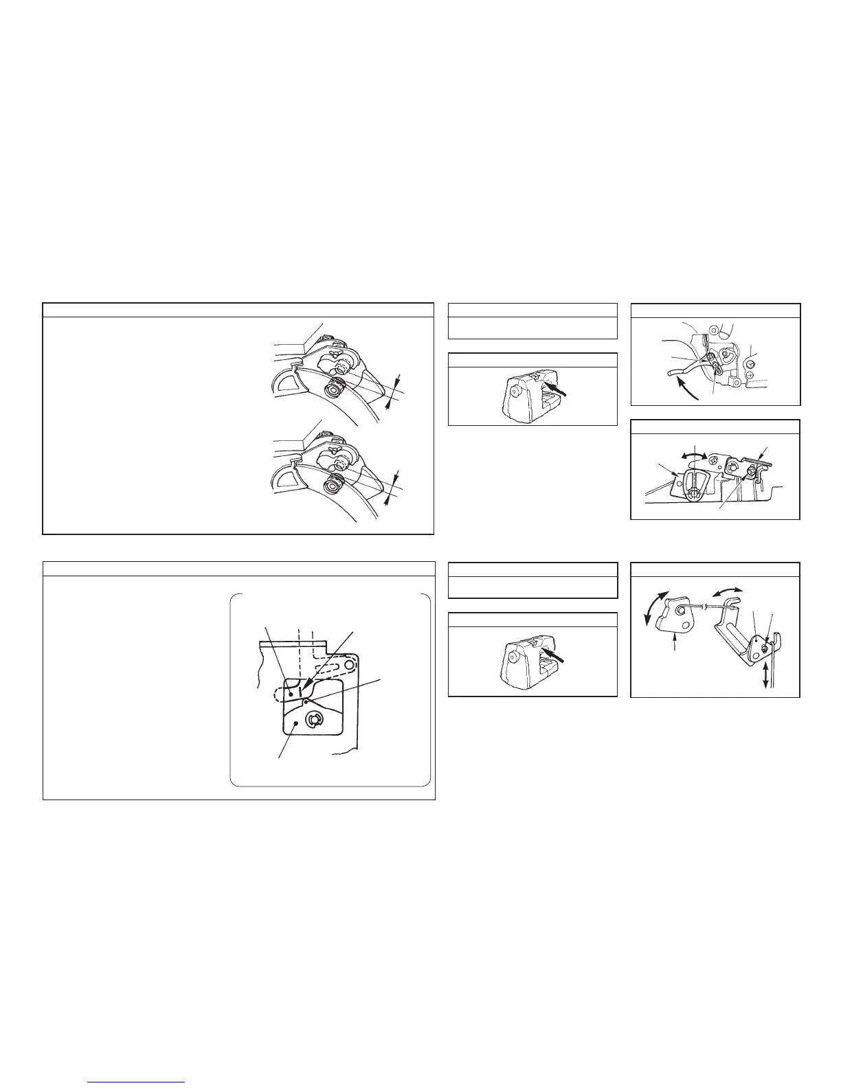
[Presser lifting lever] Adjustment drawing (A)
Loosen screw 1 and move 2 up or down. Then adjust
so that the extension amount between the drawing
roller and the auxiliary roller should be 3 to 5 mm when
the presser lifting lever is raised.
[Thread release cam] Adjustment drawing (B)
Loosen screw 4, turn 5, and adjust so that the
extension amount between the drawing roller and the
auxiliary roller should be 4 ± 0.5 mm when thread
release cam 3 is turned and the center rib is brought
to the highest position.
(7) Extension amount between the drawing roller and the auxiliary roller
How to adjust Disassembly
Location of components to be adjusted
Adjustment drawing (A)
3 to 5 mm
4 ± 0.5 mm
A to F on pages 15 and 16
When cam rib is hingest.
Adjustment drawing (B)
How to adjust
Disassembly
Location of components to be adjusted
Adjustment drawing
(8) Base tension
A to F on pages 15 and 16
Projection
Base tension floater
Marker line
Thread
release cam
• Connect the SW jig for testing to CN1 of
the microcomputer circuit board.
• Turn ON SW-C in the SW jig for testing on
P45, and the lateral feed STM rotates to move
the thread release cam to psition 2.
At this time, loosen screw 2 in the thread
release link adjusting plate, turn thread
release adjusting plate 1 and adjust so
that the projection of thread release cam
3 is positioned to the marker line on the
base tension floater as shown in the figure.
Observe from the lightning hole of the
drawing STM installing plate on the from side
of the sewing machine.
1
2
3
4
5
1
2
3