22
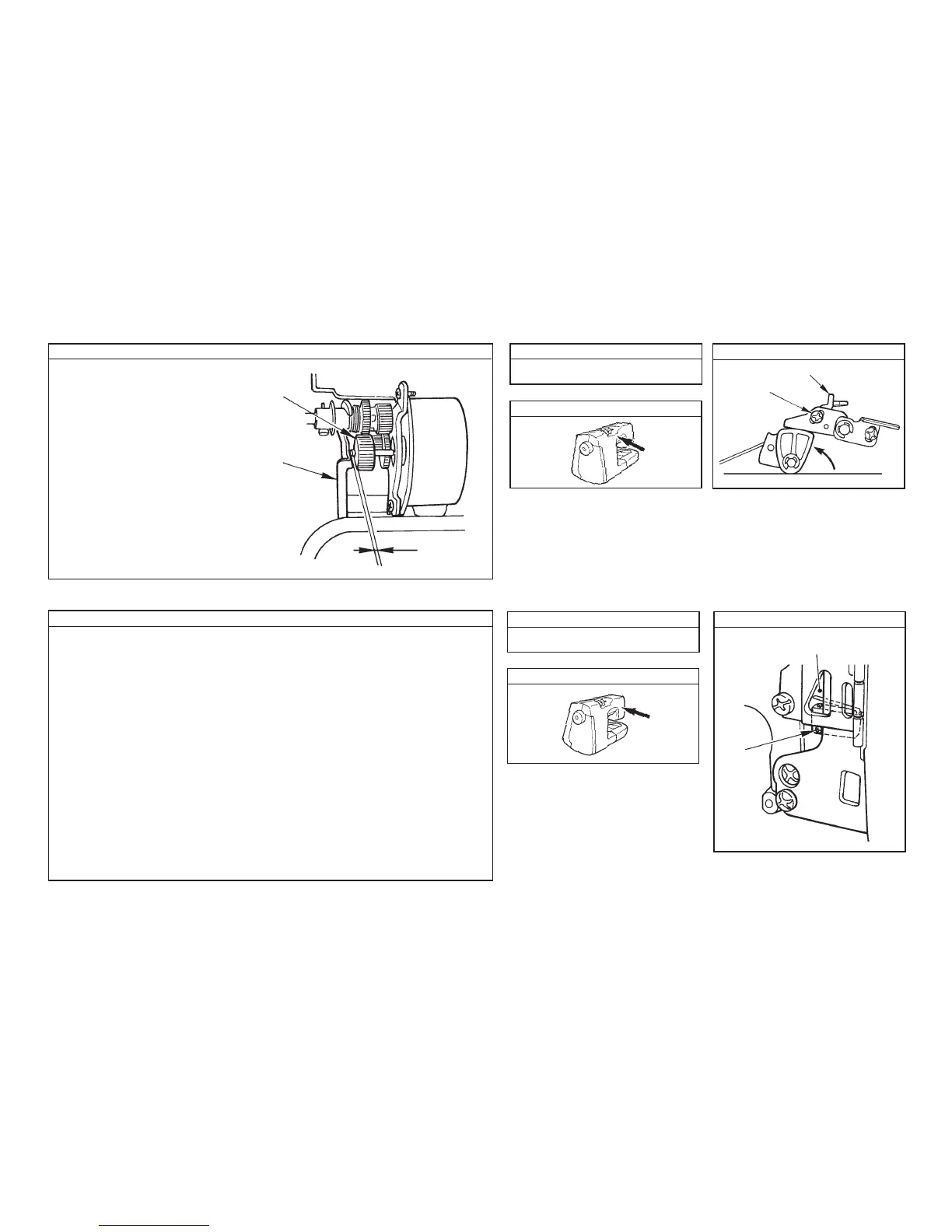
(9) Change-over of the drawing STM
How to adjust Disassembly
Location of components to be adjusted
Adjustment drawing
Connect the connector of the front panel only,
set the main shaft to 180˚, and turn ON “S”
of the service mode in the state that the front
panel and the rear panel are removed.
The lateral feed STM rotates and the thread
release cam turns.
At this time, loosen screw 3 and adjust with
4 so that the clearance provided between
1 and 2 should be 1 -2 mm.
(10) 1 stitch switch
A to F on pages 15 and 16
Adjust while looking from this hole.
This switch detects the UP state of the presser lifting lever.
• When the presser lifting lever is UP, the 1 stitch SW should be pressed.
• At this time, the clearance between the lever and is “0” and the lever should notpress the
switch excessively.
• When the presser foot is in DOWN position, the switch should not be pressed.
Loosen screw 1 and move the switch to meet these conditions.
A to F on pages 15 and 16
How to adjust
Disassembly
Location of components to be adjusted
Adjustment drawing
1 to 2 mm
1
2
3
4
1