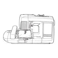
15
D. Under cover
• Loosen screws 1 and 2.
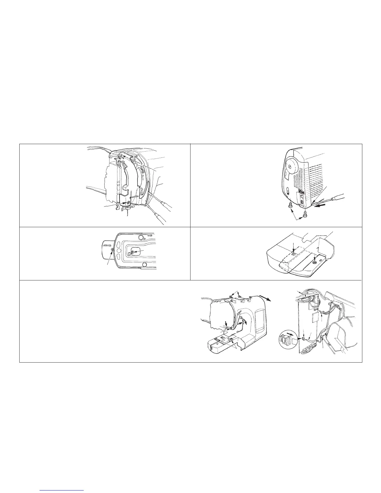
B. Belt cover
• Remove screws 1, slantly insert
a thin screwdriver into the hook-
ing section C and push in the di-
rection of arrow mark to remove
the cover.
A. Face plate cover
• Loosen screws 1 and 2.
• Remove claw section A and B
using a thin screwdriver or the
like.
[4] How to disassemble the frame components
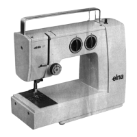
C. Free arm bottom cover
• Loosen screws 1 and 2.
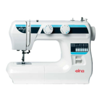
E. Front panel
• Loosen screws 1 and remove the needle plate.
• Remove screws 2 and loosen screw 3.
• Drawing section A in the -> direction, insert a thin screwdriver into section C and
remove the claw.
• Applying force to section A in the -> direction, insert a thin screwdriver into section D
and remove the claw.
• Remove claw section E located at the jaw section while lowering the rear panel.
• Remove connectors 4, 5, and 6 connected from the front panel to the microcom-
puter circuit board.
• When drawing out the flexible card connector 7, draw it out after lock of connector
6 has been released.
• Remove connector 8 connected to the inverter circuit board.
A
B
E
C
A
B
C
2
1
1
1
2
1
2
3
4
5
6
7
2
2
D
1
8