49
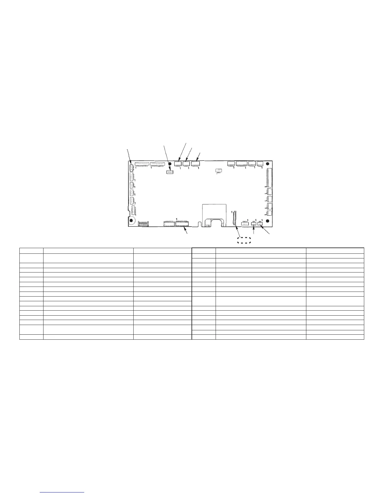
[6] Circuit board connection diagram
[Microcomputer circuit board]
CN1
CN2
CN6
CN7
CN8
CN9
CN3
CN4
CN5
CN11
CN12
CN13
CN14
CN21
CN29CN35
CN30
CN31
CN32
CN33
CN34
CN26 CN25
CN24
CN20
CN19
CN18
CN16
CN23
Table of microcomputer circuit board connector
Connector No.
CN-1
CN-2
CN-3
CN-4
CN-5
CN-6
CN-7
CN-8
CN-9
CN-11
CN-12
CN-13
CN-14
CN-16
CN-18
CN-19
Connection
S/S, thread trim, reverse feed, with/without exclusive bobbin thread,
etc.
Potentiometer
Buttonholing SW
Motor pulse
Presser lifting SW
Disengagement detecting circuit board
Needle throw STM
Threading STM relay lead wire, transfer body detecting circuit board
With/without needle thread detecting circuit board
Thread wind SW
Motor thermistor
Terminal used at the time of production
Display circuit board relay lead wire
Needle thread breakage detecting circuit board
Bobbin thread origin sensor circuit board, thread retaining plate cover
sensor circuit board
Bobbin thread supply STM
Check
9PIN 3.3V ; 12PIN 5V ; 3.11PIN GND ;
14PIN 270Ω
1PIN 3.3V ; 3PIN GND
2PIN GND
1PIN 5V ; 3PIN GND
1PIN 5V ; 3PIN GND
1-2PIN, 3-4PIN 4.2Ω
1-2PIN, 3-4PIN 10Ω ; 5PIN 5V ; 7PIN GND
1-2PIN, 3-4PIN 4.2Ω
1PIN-GND
For assembling
2PIN 20 to 24V ; 7PIN GND ; 6PIN 5V
1PIN 5V ; 2PIN-GND 270Ω
1,5PIN GND ; 3PIN 5V
1-3PIN, 2-4PIN 20Ω
Connector No.
CN-20
CN-21
CN-22
CN-23
CN-24
CN-25
CN-26
CN-27
CN-28
CN-29
CN-30
CN-31
CN-32
CN-33
CN-34
CN-35
CN-36
Connection
Feed STM relay lead wire
Embroidery card connector
ROM adaptor
Serial communication connector
Touch panel connecting wire
Driver binding wire A
Driver binding wire B
ROM adaptor
ROM adaptor
Controller socket, card lid SW circuit board, light and shade VR circuit
board
Power circuit board connecting wire
Remaining amount sensor circuit board (receiving light)
Remaining amount sensor circuit board (emitting light)
Lateral feed STM relay lead wire
Main shaft detecting circuit board
Power supply connecting wire
DF sensor circuit boad
Check
1-2PIN, 3-4PIN 4.2Ω
1, 10, 11, 18, 23PIN GND
25PIN 3.3V ; 15, 34PIN GND
1PIN GND
7, 9PIN GND
5PIN 5V ; 1, 3, 7PIN GND
1-3PIN 16.8V
2PIN 5V
2PIN GND
1-2PIN, 3-4PIN 10.5Ω
2PIN 5V ; 5PIN-GND
2-1PIN 5V ; 4-3PIN 30V ; 6-5PIN 34V
Replacing the microcomputer circuit board
CN36
• Be to turn the power OFF when inserting /
drawing out the connector of [CN14].
• Securely insert the connector until it will
go no further when inserting it.
LCD will be caused to break.