Do you have a question about the ELNA E9020 and is the answer not in the manual?
Details sewing machine speed control, ranges, and soft start function.
Describes key mechanical components like hook, feed, lighting, and presser foot.
Explains needle bar rocking, straight/zigzag stitching, and width adjustment.
Covers feed amount, reverse stitching, and lateral feed adjustments for material movement.
Details automatic thread control, trimmer, backtack, buttonholing, and sensors.
Lists microcomputer specs, memory types (Flash, ROM), and embroidering card compatibility.
Provides physical specifications for the main unit and embroidery device.
Specifies voltage and frequency requirements for the sewing machine unit.
Details sewing speeds for different stitch types, patterns, and operations.
Explains how the start/stop switch controls machine operation and needle position.
Describes using the foot controller for starting, stopping, and speed regulation.
Explains the process of automatic needle and bobbin thread trimming.
Details the procedure and conditions for automatic bobbin winding.
Describes the function and display message related to the presser foot lift.
Explains how to select patterns using the touch panel and LCD.
Describes how the needle throwing STM controls needle movement via links.
Explains longitudinal and lateral feed mechanisms driven by STMs.
Details how reverse stitching is activated for regular and lateral feed patterns.
Covers how the embroidery device uses feed STMs for pattern stitching.
Explains the system for automatically controlling needle thread tension.
Details pattern storage, saving, and calling functions.
Explains the process of disengaging the main shaft rotation.
Describes the step-by-step process of automatic needle threading.
Details the guide for automatic bobbin thread winding from exclusive thread.
Lists common issues like defective thread tension and stitch skipping.
Covers thread breakage, hitched stitches, and defective material feed.
Addresses needle contact problems and incorrect pattern shapes.
Indexes problems related to automatic thread trimmer, noise, and buttonholes.
Lists common problems with the bobbin winder and needle threader.
Pertains to issues specifically related to the embroidery device.
Provides troubleshooting steps for common issues with automatic needle threading.
Offers solutions for various problems encountered during automatic bobbin winding.
Instructions for removing the face plate, belt, free arm bottom, and under covers.
Details the steps for removing and disconnecting the front panel components.
Covers the process of removing the rear panel, bottom plate, and related parts.
Instructions for taking apart the frame of the embroidery device.
How to adjust the needle's path for correct stitch formation.
Adjusting presser bar height and the position of the presser foot.
Critical adjustment for synchronizing needle and hook movement.
Adjusting the precise gap between the needle and hook blade.
Adjusting the longitudinal position of the inner hook detent.
Setting the correct height for the feed dog mechanism.
Adjusting the extension between drawing and auxiliary rollers.
Adjusting the base tension floater for proper thread control.
Adjusting the drawing stepping motor change-over mechanism.
Adjusting the switch that detects the presser lifting lever state.
Adjusting the position of the looper relative to the moving knife.
Adjusting the play in the knife disengagement mechanism.
Lateral adjustment of the thread trimming cam.
Adjusting the upper and lower moving knife guide plates.
Adjusting the height of the looper for thread trimming.
Procedure for measuring and adjusting bobbin thread tension.
Adjusting the longitudinal position and tension of the timing belt.
Adjusting the buttonholing switch for precise stitch placement.
Adjusting the clearance and position for main shaft disengagement.
Adjusting the tension of the motor timing belt.
Adjusting the needle threader mechanism and its components.
Detailed adjustments for various parts of the automatic needle threading system.
Step-by-step adjustments for the automatic bobbin winding mechanism.
Adjusting the position of the DF sensor circuit board for correct operation.
Adjusting clearances for hook driving shaft supports A and B.
Adjusting the main shaft support and main shaft upward bend.
Setting the position of the driving gear cover.
Steps for replacing the motor in the embroidery device.
How to adjust belt tension for the embroidery device's drive shafts.
Setting the origin point for X and Y drive mechanisms using sensors.
Adjusting mode change-over and embroidering device detection switches.
Illustrates the electrical connections for the embroidery device components.
Lists available service mode functions and their descriptions.
Steps to navigate and set panel switches within the service mode.
How to enter the service mode and perform confirmations.
Procedures for confirming settings like feed compensation and pattern adjustments.
Detailed steps for various service mode checks like needle positions and thread trimming.
Procedures for checking card insertion, lid status, and sensors.
General instructions for performing tests using the switch jig.
Specific tests for memory, LCD, ROM, and flash using switches.
Table detailing connectors, their purposes, and checks.
Visual representation of the microcomputer circuit board and its components.
Steps for safely replacing the power circuit board.
General instructions and specific fuse types for replacement.
Procedures for replacing filter board fuse, transformer, and main motor.
Wiring diagram for the display circuit board and its connections to other components.
| Brand | ELNA |
|---|---|
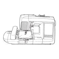
| Model | E9020 |
| Category | Sewing Machine |
| Language | English |