- 19 -
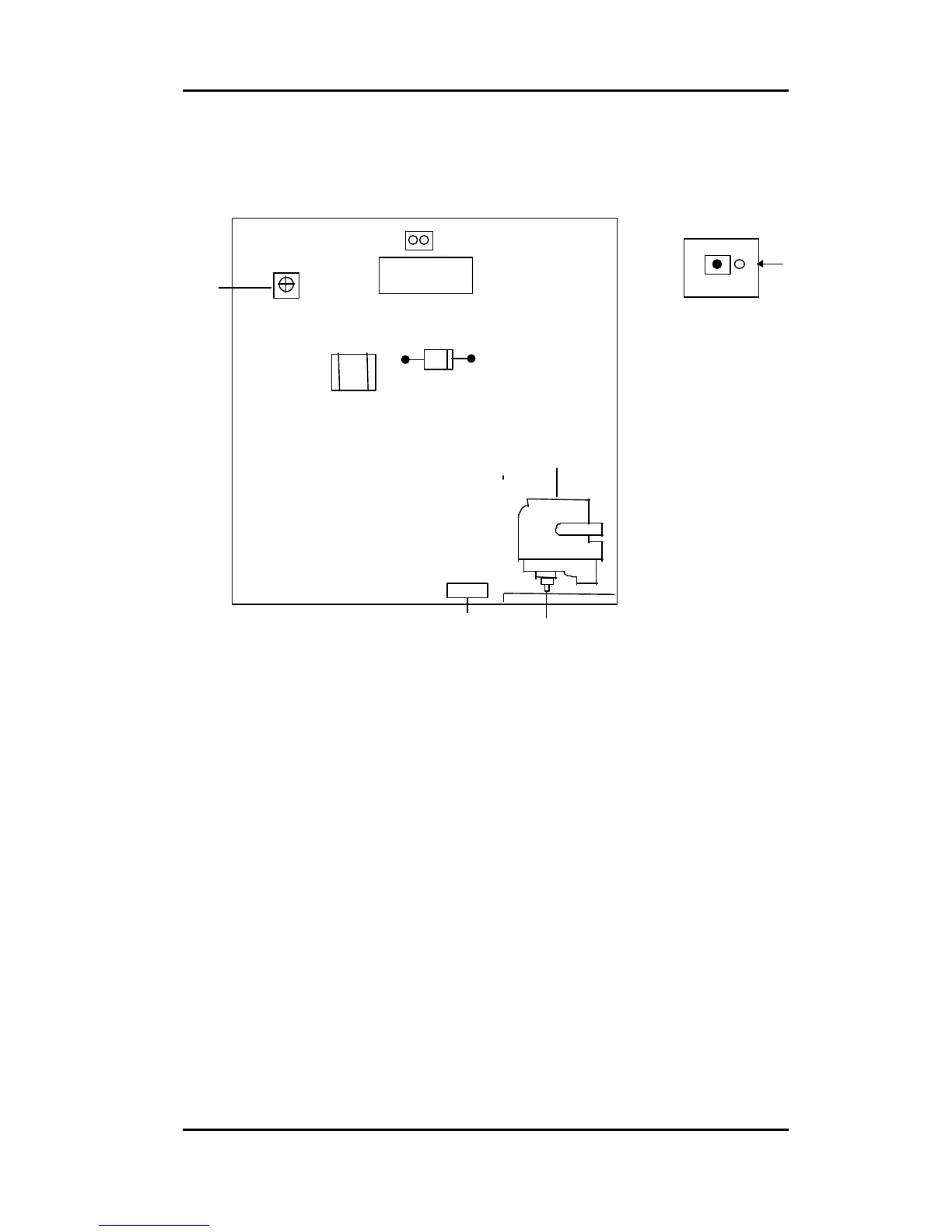
6. Service Adjustment Control Locations
7. Adjustment
7-1 B+Voltage Adjustment:
-Apply the mode 3 signal with a full white pattern.
-Apply 220V AC to the unit.
-Set the Brightness and the Contrast to the Max, the display size to 270mm×
202mm for 15” , 300×225mm for 17” , 350mm×262mm for 19”.
-Apply the mode 4, the display size to 317 mm×237mm for Atronic model only.
-Apply the mode 1~7, the display size to 317 mm×237mm for ET17 Bally mode only
Size 350 mm×262mm for 19”.
-Apply the model 1~7, the display size to 356 mm×264mm for ET19 Bally model
only.
-Apply the mode 8 , 9, adjust the H-Size to 90% (OSD) with adjust the SUB H-Size
to 358 mm×268mm for ET1988C-4SWA-1-SEGA TPS model only.
-Put the DVM probe between D615 cathode and GND.
-Adjust the VR601 until 14.7 VDC +/-0.1V.
-Put the Hight Voltage DVM probe between the H.V. Cap and GND.
-Adjust the VR501 until 23.5 +/- 0.1KV (15”).
-Adjust the VR501 until 24.5 +/- 0.1KV (17”).
-Adjust the VR501 until 24 +/- 0.1KV (19”).
-Adust the screen VR until G2 to 550V ±10V (15” only)
1.
LED
2. OSD Function key ( SW5 )
2,3 Focus
4. H.V.Voltage (VR501)
6. B+ (VR601)
5
VR601
T601
F.B.T
Part sideview-Main Board
2,3