Do you have a question about the Elo TouchSystems ET1587C and is the answer not in the manual?
Details safety requirements for voltage, frequency, current, and operator-serviceable parts.
Covers compliance with FCC, Industry Canada, and EU CE regulations regarding radio frequency energy.
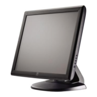
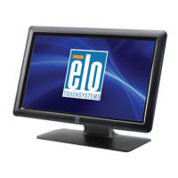
Highlights key features of the touchmonitor, including display size, touch technology, and connectivity.
Explains the benefits of touchscreen technology for user interaction and transaction efficiency.
Details Elo's iTouch surface wave technology, featuring touch-on-tube, no overlay, parallax-free, and enhanced durability.
Provides details on the touchmonitor's power connector pinout and pin assignments.
Lists technical specifications for 15", 17", and 19" monitors, covering display and input parameters.
Details mechanical properties like positional accuracy, touchpoint density, and durability.
Details optical specs: light transmission and visual resolution.
Covers chemical resistance and electrostatic protection standards for the touchmonitor.
Provides a diagram and list of signals for the monitor's signal connector pins.
Instructions for checking the contents of the package to ensure all items are present.
Important safety instruction to power off devices before connecting cables.
Guidance on connecting the video cable between the monitor and PC, including securing the connection.
Instructions for connecting the serial touchscreen cable between the monitor and computer.
Details on connecting the power cable and protecting the unit from power surges.
Information on installing Elo TouchSystems driver software from the included CD-ROM for various Windows versions.
Step-by-step guide for touch driver installation on various Windows versions.
Instructions for installing the touch driver in MS-DOS and Windows 3.1 environments.
Information that factory settings are optimized, but user adjustments are possible.
Explanation of how to use the OSD knob to adjust screen display settings.
Guidance on accessing, navigating, and making adjustments within the OSD menu.
Detailed descriptions of various OSD adjustment functions for image quality and display settings.
Details the required input voltage and frequency for proper monitor operation.
Procedure for verifying monitor settings after adjustments, including brightness and contrast.
Lists specialized equipment recommended for performing monitor adjustments.
Procedure for adjusting the B+ voltage, including required test patterns and measurement points.
Procedure to test the monitor's X-ray protection circuit functionality.
Method for adjusting the focus using specific potentiometers on the FBT for optimal image clarity.
Steps for aligning white balance using a color analyzer and OSD controls for accurate color reproduction.
Adjustments for trapezoid, pincushion, and rotation distortion using OSD controls.
Procedures for adjusting geometric parameters and performing quality control checks.
Specifies signal level, sync, and input impedance requirements for monitor performance.
Defines standards for display area dimensions, centering, and various types of geometric distortion.
Specifies display area dimensions and range for different CRT sizes based on preset timings.
Defines acceptable limits for display centering relative to the monitor bezel.
Sets tolerance limits for trapezoid, parallelogram, pincushion, and barrel image distortions.
Specifies the acceptable tolerance for image rotation (H1-H2).
Defines the primary test mode for 15" monitors to check linearity.
Defines the primary test mode for 17" and 19" monitors to check linearity.
Specifies linearity requirements for modes not covered by primary test modes.
Covers video output bandwidth, luminance, uniformity, display area regulation, and color point.
Specifies the bandwidth of the video output signal.
Defines acceptable luminance levels and conditions for various display states.
Specifies the minimum acceptable luminance uniformity percentage.
Details acceptable variations in display area due to luminance, power, and temperature.
Defines acceptable color point coordinates (x,y) for white display.
Specifies maximum allowable misconvergence for both center and corner areas of the display.
Defines criteria for visible mislanding on the CRT surface and display area.
Specifies uniformity requirements for color coordinates across the white display.
States that image jitter should be invisible at a distance of 60 cm from the CRT surface.
Troubleshooting steps for power, LED status, keyboard connection, and video configuration issues.
Check VESA DPMS standard compliance from computer or graphics adapter.
Check refresh rate against recommended modes; flickering may occur below 75Hz.
Recommend degaussing and checking monitor distance from electrical equipment.
Verify good connection between touchmonitor and computer.
Refer to manual for adjusting monitor picture and making adjustments.
Readjust brightness and contrast settings.
Verify video adapter settings for correct resolution and refresh rates.
Indicates graphics adapter or touchmonitor issue; contact service.
Check PC power, connection, and video cable for no video signal.
PC signal exceeds monitor capability; adjust PC display settings to a supported mode.
Ensure touchscreen cable is securely attached at both ends.
Procedure for safely discharging high voltage from the CRT anode before servicing.
Illustrates the power supply circuit, including AC input, filtering, rectification, and output stages.
Flowchart for diagnosing power supply issues, checking voltages, components, and circuits.
Flowchart for diagnosing issues when the LED is flashing, checking H-Driver T.R., DC-DC circuit, and shorts.
Flowchart for diagnosing noise issues, checking U601, T601, C620, and D612.
Flowchart for diagnosing no high voltage: checking D509, R641, sync signals, and related ICs.
Flowchart for diagnosing no raster: checking SMPS output, horizontal deflection, FBT, and CRT heater/cathode.
Flowchart for diagnosing issues with horizontal lines only: checking U301 outputs and V. Yoke.
Flowchart for diagnosing H. Mode Error: checking VR501, Q501 voltages, and U101 DAC pin.
Flowchart for diagnosing V. Mode Control Error: checking U101 pin 32 and U201 pins.
Flowchart for diagnosing Hold Down issues: checking B+ voltage, U201 pin 29, and related transistors.
Flowchart for diagnosing no video start: checking power supplies, signals, and video circuits.
Steps for diagnosing CPU malfunction: checking pin voltages, oscillation, and front panel controls.
Diagnosing OSD malfunction: checking control keys, pin voltages, and related ICs.
Troubleshooting E2PROM storage failure: checking power supply, soldering, and component replacement.
Troubleshooting for CS signal issues: checking power circuit, sync signals, and CPU functionality.
Troubleshooting screen noise during mode changes: checking power, U101 pin 16, and transistor.
Listing of resistor types with their corresponding allowances and descriptions.
Listing of capacitor types with their corresponding allowances and descriptions.
List of common parts for ET15 models, including circuit reference, description, and part number.
| Brand | Elo TouchSystems |
|---|---|
| Model | ET1587C |
| Category | Monitor |
| Language | English |