13
www.elstat.io
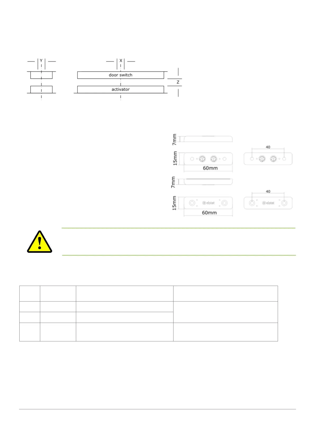
The diagram shows the horizontal, vertical, and gap alignment between the door switch and the activator for open
and closed doors.
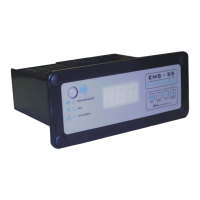
4.2 How to mount the enhanced door switch
Door switches are usually mounted with the door switch
on the cooler and the activator on the door. Door switches
and activators must be fixed using counter sunk screws
or bolts with the following characteristics:
• Head: countersunk head maximum diameter 6.0mm
(0.236in) and minimum diameter 5.0mm (0.196in)
• Thread: maximum diameter 3.0mm (0.118in)
The screws must be tightened to a maximum torque of
0.5Nm (0.37lbfft).
Alignment Dimensions Notes
X Horizontal 0mm (0in) +/-20mm (0.7in)
measured when the door is closed and
the gap (z-dimension) is correct
Y Vertical 0mm (0in) +/-10mm (0.4in)
Z Gap
0mm (0in) to 5mm (0.2in) +/-2mm
(0.07in)
The alignment of the door switch and activator is critical for the correct operation of the door switch. The following
table details alignment tolerances.
Note
Door switches and activators supplied by elstat must not be installed using rivets. Using rivets
invalidates the warranty.