____________________________________________________________________________________
____________________________________________________________________________________
14 NTU Optical Network Terminals
RJ-11 port for connecting analogue phone
4 RJ-45 ports for connecting network devices
Wi-Fi enabling/disabling button
enables automatically protected Wi-Fi connection for the device
functional key that reboots and resets the device to the factory settings
SC port (socket) for PON with GPON interface
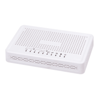
Figure 7 shows the NTU-RG-1421GC-Wac front panel layout.
Figure 7 – NTU-RG-1421GC-Wac front panel layout
Table 7 lists LEDs located on the device front panel.
Table 7 – Description of the LEDs located on the front panel
power and activity status indicator
configuration and hardware status indicator
Ethernet port activity indicator
Wi-Fi activity indicator for 2.4 GHz
Wi-Fi activity indicator for 5 GHz
FXS port activity indicator
2.6 LED Indication
2.6.1 NTU-RG-1421G-Wac, NTU-RG-1421G-WZ, NTU-RG-1431G-Wac
LED indicators located on the front panel represent the current state of the device.
Possible states of the LEDs are listed in Table 8.
Table 8 – Light indication of the device
10/100Mbps connection has been established
1000Mbps connection has been established
 Loading...