____________________________________________________________________________________
____________________________________________________________________________________
VoIP subscriber gateways 15
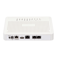
2.6.2 Rear panel of the device
The rear panel layout of the device is depicted in Fig. 5.
Fig. 5 – TAU-8.IP-W rear panel
The following connectors and controls are located on the rear panel, Table 4.
Table 4 – Description of the connectors and controls on the rear panel
Connector for Wi-Fi-antennas
1
connection
Connector to connect power adaptor
USB connector for external memory connection
8×RJ-11 connectors for analogue phone connection
10/100BASE-T port, 100BASE-TX (RJ-45 connector) for connection to
external network (WAN)
Functional button to reboot and reset the device settings to the default
2.7 Light indication
Wi-Fi
1
, WAN, Phone and Power LEDs display current state of the device located on the front panel.
Status list of indicators is shown in Table 5 and 6.
Table 5 – light indication of the device
Data transfer process by using wireless network
Green (10 Mbps)or orange (100 Mbps)
Connection is established between station
terminal and subscriber terminal
Packet data transmission process by using
 Loading...