2002 by ELTRA GmbH Germany – January 2002 – Service Manual OH 900 / ON 900 / ONH 2000
2.3-1
2.3
2.3
Infrared zero-baseline, control and adjustment:
The infrared cell zero-baseline is normally controlled by the electronic and is automatically
set to zero.
The auto–zero control should be disabled in order to control and adjust the infrared cell
zero-baseline manually. This way the electronics will have no influence. This can be done
by pressing the < Menu > and < Cal > keys.
The voltage exiting the infrared channel should be shown as in the following example:
- 0.13
- 0.21
- 0.18
The displayed numbers refer to the IR-cell output voltage:
The upper number refers to the voltage of channel 1
The middle number refers to the voltage of channel 2
The lower number is valid for the voltage of channel 3 ( if there is a channel 3 ).
The channel numbers can be shown on the display by pressing: < Menu > < 5 >
Return by pressing < CLR >.
If at least one voltage exceeds +3.0 volts, then the zero-signal needs to be adjusted.
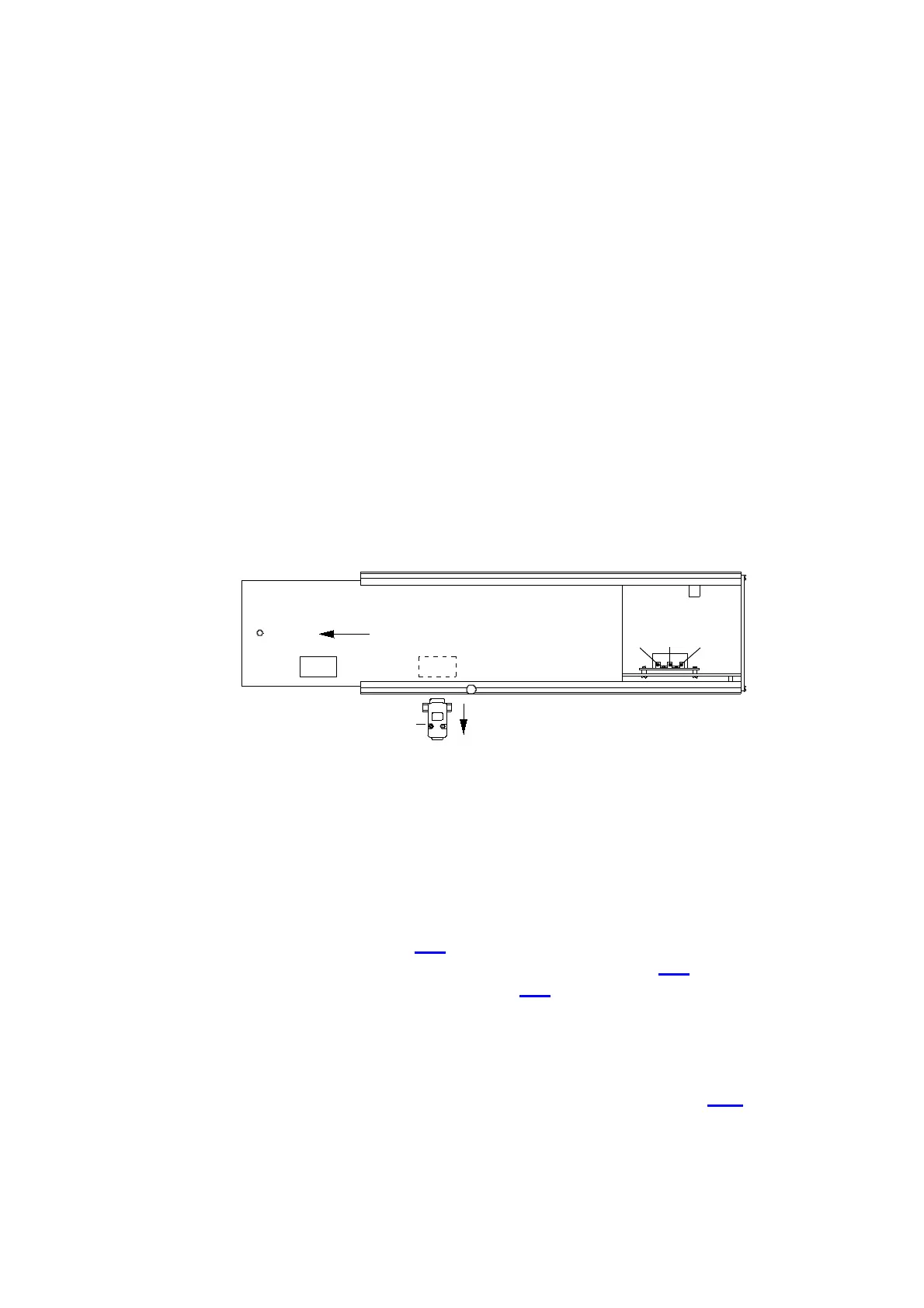
To adjust the zero signal, push the left cover plate ( 2 ) of the infrared cell about 10 cm
towards the back.
With a small screwdriver, adjust the trimmers ( 3 / 4 / 5 ) in the infrared rack, so that
the numbers shown on the display are between + 0.20 and - 0.20.
The adjustment should preferably be carried out while the carrier gas is flowing.
If the zero level ( between + 0.20 and - 0.20 volts ) cannot be reached, and if more
than two adjustments were recently carried out, then the problem could be:
Contamination of the IR-paths, see 3. 1
bending of the IR-source after rough shipment of the device, see 3. 2
insufficient supply voltage for the Infrared, see 2. 4
The stability of the displayed numbers should be better than ±0.01:
■ Normally, the second digit after the decimal point does not change, or it may
fluctuate up and down by only 1, since this could be actually on the rounding point.
If the fluctuations are larger, then there is a major degree of noise, see 1.16.
The drift should also be very small. Within 10 minutes the second digit after the
decimal point should not change more than 1.
The drift should first be checked when the analyser has been switched on
( power switch on setting 1 ) for at least one hour, better would be two hours, and
an oxygen flowed for about 10 to 15 minutes ( Power switch on setting 2 ).
4
2
3 5
2-3-1 S
1