2002 by ELTRA GmbH Germany – January 2002 – Service Manual OH 900 / ON 900 / ONH 2000
2.6-1
2.6
2.6
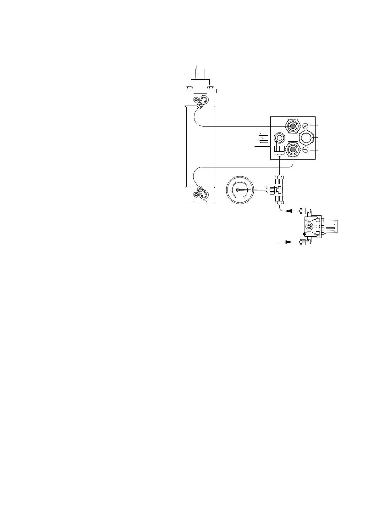
Pneumatics for furnace lift:
1 Pneumatic valve
2 Upward speed regulator
3 Muffler
4 Downward speed regulator
5 Pressure gauge max. 2.5 bar ( 30 psi ). ( Lower gauge on the front panel )
6 Pneumatic cylinder
7 upper cushioning
8 lower cushioning
9 Compressed air inlet 4 to 6 bar ( 60 - 90 psi )
( on the rear panel on the right hand side )
10 Pressure regulator
11 Furnace lift
The pressure regulator ( 10 ) needs to be adjusted first.
After removing the side panel on the right-hand side of the analyser, the pressure is
set by pulling and rotating knob ( 10 ), until the correct value of 2 bar is displayed on
pressure gauge ( lower gauge on the front panel ).
The upward speed of the furnace lift ( 11 ) is set with the screw ( 2 ).
The speed of the final travel before the upper stop is set with the screw ( 7 ).
The downward speed of the furnace lift ( 11 ) is set with the screw ( 4 ).
The speed of the final travel before the lower stop is set with the screw ( 8 ).
CAUTION !
When the screw ( 7 ) for final upward travel is too tightly screwed, it can happen that
the furnace doesn't close ( speed = zero ).
3
4
2
9
5
7
8
11
2
6
1
2 b a r / 3 0 p s i
0
1,5
10
2 - 6
 Loading...


