2002 by ELTRA GmbH Germany – January 2002 – Service Manual OH 900 / ON 900 / ONH 2000
2.18-1
2.18
2.18
Sample drop motor and the motor switch adjustment
Detailed explanations
This description applies to the case of an analysis cycle running correctly, which means
from the operation of the < START > button to the end of the analysis; when the results
appear on the PC screen or the printer. During that time the sample drop motor has
performed a full rotation.
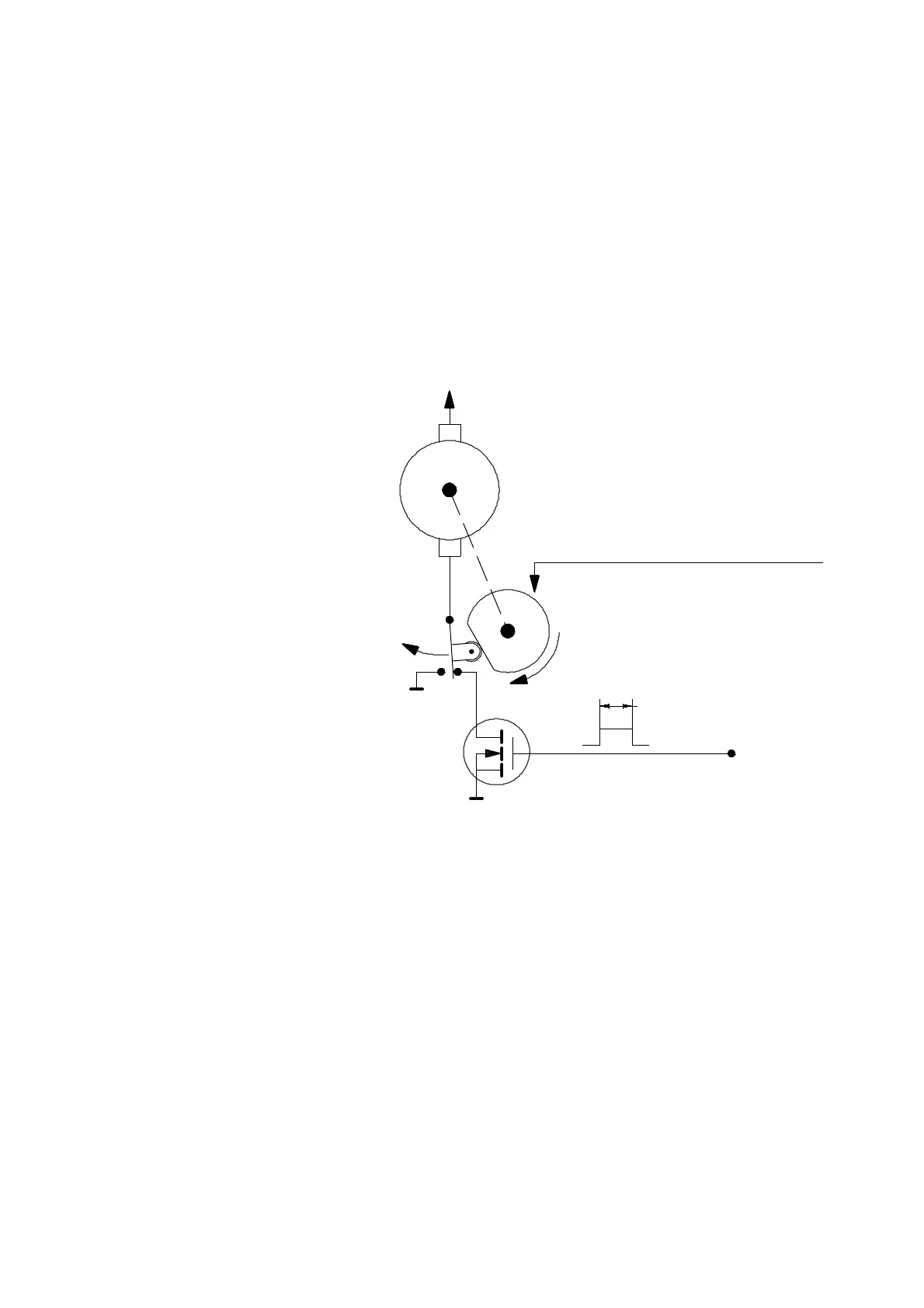
Way of operation
This simplified diagram shows
the sample drop system and
related circuit
The PLUS connector of the sample drop motor is directly connected to +24V DC.
When the time is right for the sample drop motor to turn, the transistor is activated
by the electronic rack software.
The switching transistor connects the MINUS lead of the motor to GND.
The motor starts turning, and shortly thereafter the eccenter of the motor shaft
presses the switch.
From now on the motor is connected to GND via the switch and not through
the transistor.
Before the motor makes a full turn, the transistor is deactivated by the electronic
controller.
The motor keeps on turning, still connected to the GND via the switch.
When the motor has made a full turn, the eccenter will release the switch.
The MINUS connector of the motor is now disconnected from the GND
and it is connected to the transistor again.
The transistor, however, is no longer activated, so that the motor stops turning.
+24V DC
+
G
2 seconds
from the
MOTOR
electronic rack
Control signal
S
D
GND
GND
-
Eccentric wheel on motor shaft
4 seconds for one turn
1-14-2
IRF820
TRANSISTOR