2002 by ELTRA GmbH Germany – January 2002 – Service Manual OH 900 / ON 900 / ONH 2000
2.1-1
2
2
ADJUSTMENTS, TEST AND FUNCTION EXPLANATION
2.1
2.1
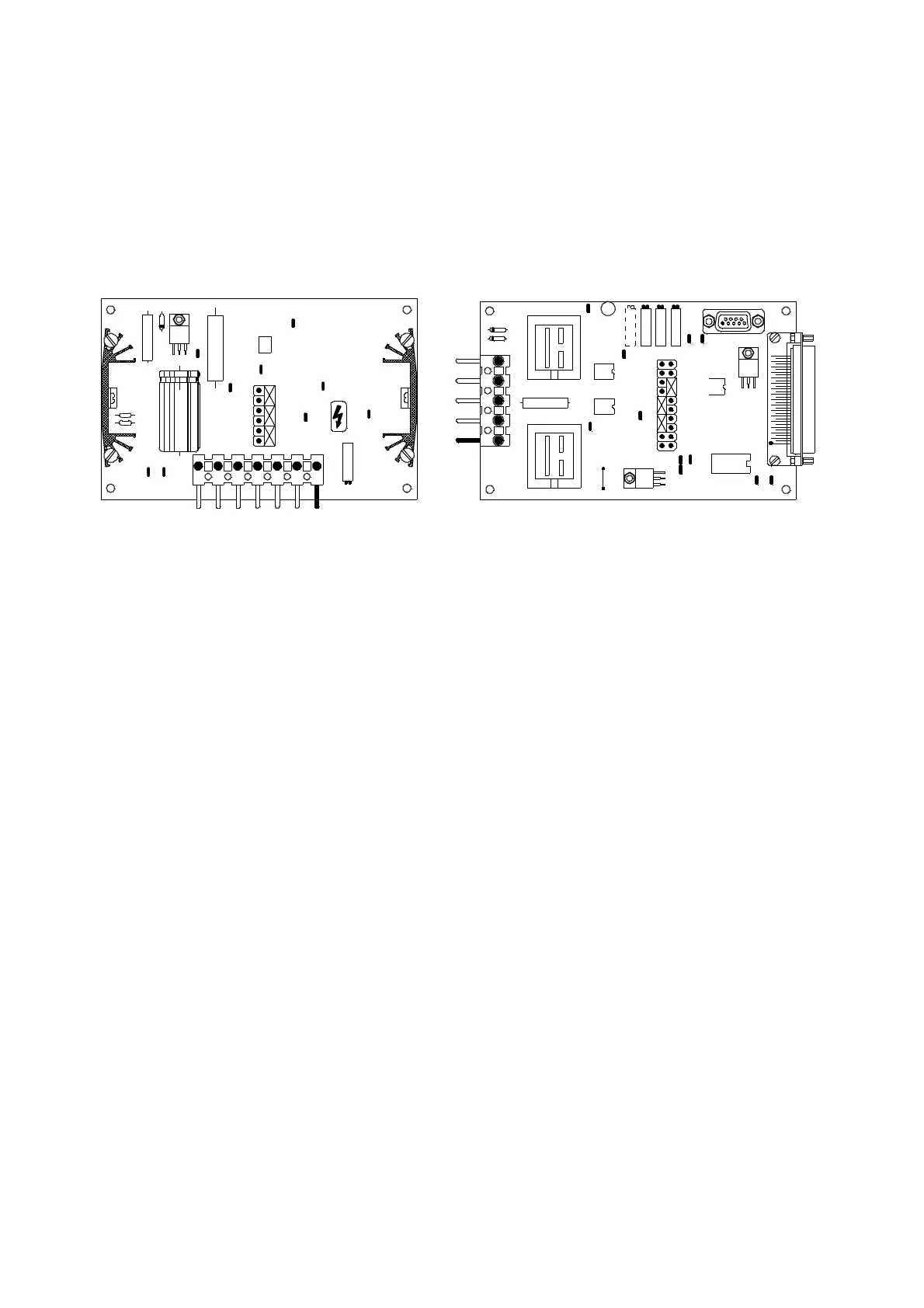
Gas flow controller adjustment and jumper settings:
The jumpers of the pump control board The jumpers of the flow control board
NR 32 are set FC 21 are set
B1-B2 B3-B4 B5-B6 B3-B4 B5-B6 A7-A8
Make sure the gas pressure is available.
Set the main power switch to pos. 2
Read 1.5 bar carrier gas pressure on the pressure gauge of the analyser.
Adjust the required gas flow with P1 of the FC 21. Read the flow rate on the upper
flow meter of the analyser. The flow rate is usually between 10 l/h and 15 l/h.
Select 1000 VDC ( resp. 750 VDC ) multimeter range and connect it between TP1 and
TP 2 of the NR 32.
Adjust a minimum voltage with P1 of the NR 32.
The minimum is usually between 90 VDC and 100 VDC.
Adjust slowly to enable the flow to stabilise to the set value of the flow.
Connect the multimeter between TP8 and TP3 ( GND ) of the FC 21. Range 20 VDC.
Adjust 5.5 VDC with P2.
.
B 1
B 2
B 3
B 5
B 6
B 4
P1
T P3
TP 8
TP 2
TP4
TP 7
TP1
TP 9
NR32
15038
TP 6
TP 5
A 1
A 2
A 3
A 4
A 5
A 6
P 3 P 2 P 1
1-6-2S500
TP5
TP4
TP3
TP1
TP8 TP7
B 6
B 5
B 4
B 3
B 1
A 1
A 8
A 7
TP9
T P12
T P10
T P11
TP2
GND
15 099
CS- 50 0+ H- 5 00
FC 21
VE RSIO N