2002 by ELTRA GmbH Germany – January 2002 – Service Manual OH 900 / ON 900 / ONH 2000
2.1-2
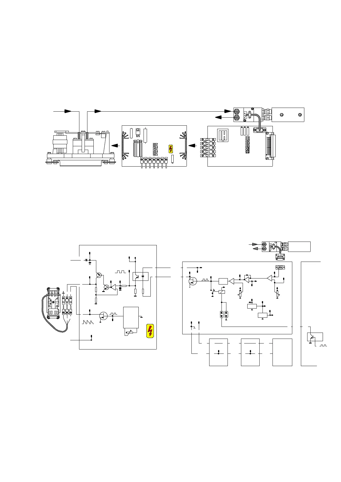
Detailed explanation of the flow controller.
The flow controller consists of four main components:
1 The flow sensor,
2 The flow control board FC21,
3 The pump control board NR32,
4 The gas pump.
■ The flow sensor senses the flow. The board FC21 compares the sensor output
voltage with the set point of the flow.
■ The output of the FC21 controls the board NR32 which is generating a variable
supply voltage for the pump.
■ The feedback from the pump to the sensor is provided by the gas flow.
In this control loop, the power of the pump is automatically regulated to keep the
sensor output at a constant value which corresponds to the set point.
■ The flow sensor, measured on TP1 of the FC 21, has an output voltage of about
5,2 VDC for an OH-900 ( 10 l/h ) and about 6,5 VDC for an ON-900 ( 15 l/h ),
depending on the flow, but also, and especially, on the number of ranges ( IR-cells ) of
the analyser. TP3 is GND.
Please note: without flow, the voltage on TP1 is not 0V, but about 0.65 V.
■ The flow rate is adjustable with the potentiometer P1 of the FC 21.
P1
14b
+5V
TP 9
TP 5
T P6
TP1 0
P2
+2 0V
+1 2V
TP 4
Re fer en ce
TP 8
Re la is
1
1 2V
Lo = f lo w Hi = n o fl ow
Exte rn a l flo w e na bl e
ELECTRONIC RACK
I C 3
13 3 0
red
black
white
red
5
9
2a
1a
TP9
GND
black
TP 3 T P 6
12 2
GN D + 2 4V
5
P 1
TP 2
TP8
T P 7
T P5TP6
TP 3
Flow s ensor
B 6
B 5
15 V
TP9
TP 2
TP 4
TP 1
T P 7
brown
16
Ju mp er s
bl ue
TP 1
7
6 00 V
br
bl
+ 2 4 V
15
7
2
3
yellow
green
controlled signal
Pu mp v oltag e
+ 2 4 V
12
1
FC2 1
12V
D r i v e r
Flow OFF
Oscillator
F lo w ON
2
8
17
ELECTRONIC
RACK boardON 21
POWER SUPPLY
NK 3 1
4
The NR32 is not insulated
from the main po wer.
The GND of the NR32 is connected
to the neut ral of the main power.
It is not the same GND as the GND
of the othe r boa rds.
CAUTION
ap p r o x 3 00 VDC
no t st a bi l is ed
Neutral
1-2-2
a p pr ox 5 0H z
blbr
220 Phase
DC pump vo lta ge
sta bilised
but con tr olled
up to 220VDC
ad ju st ment
P WM
7 8 20
78 12
b o ar d
O n
flo w
+ 2 4 V
Con tino us
flo w
+ 1 5 V
+ 2 0V
+
A 6
A 5
19a 18a
G as p u mp
NR32
2 4 V
D C
T P 4
IC4 on MP 6 800 0
IC3 o n 68k
G ND
Flow sensor
15038 15098
FC21
NR32
Feed back
Gas flow
1-2-4
Gas pump
 Loading...


