2002 by ELTRA GmbH Germany – January 2002 – Service Manual OH 900 / ON 900 / ONH 2000
2.4-1
2.4
2.4
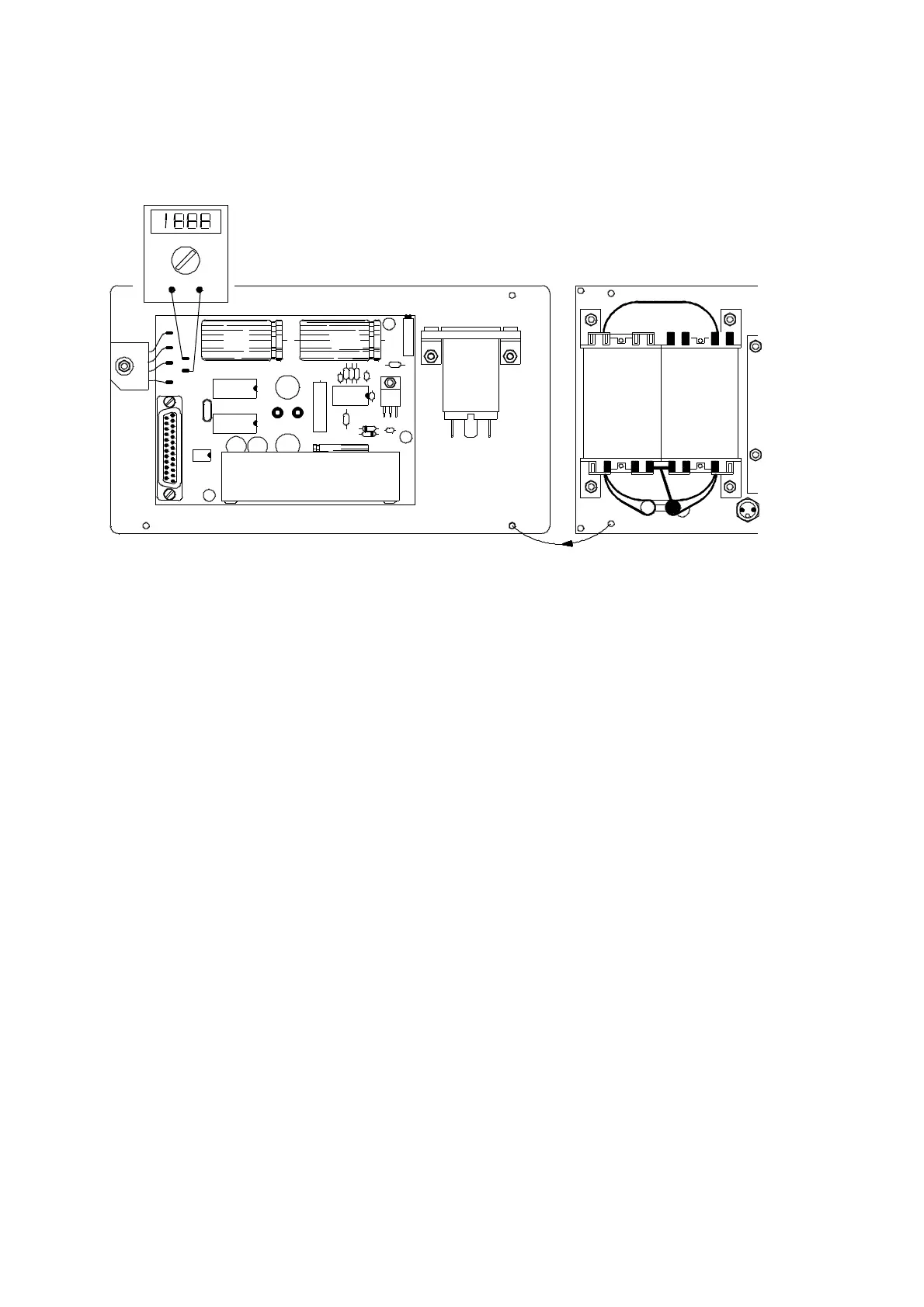
IR source voltage setting:
IR source voltage to be Transformer connections:
measured between TP1
and TP2 on IR 13 board.
1 : always connected ( common )
2 V DC for 1 channel device 2 : soldering location for 1 channel device
4 V DC for 2 channel device 3 : soldering location for 2 channel device
6 V DC for 3 channel device 4 : soldering location for 3 channel device
( 2 Volts DC for each IR source )
Set above voltages through P1
The voltage of the capacitor C must be about 5 to 6V higher than the voltage of the
IR sources measured on the a.m. test points.
If the voltage of C is too low, either the transformer is not correctly connected, or the
rectifier R is out of order.
P1
06421 IR13
C C
R
1
2
34
2- 4- 1
VD C
TP2
1
TP
I R1 3 0 6 4 20