2002 by ELTRA GmbH Germany – January 2002 – Service Manual OH 900 / ON 900 / ONH 2000
2.3-3
Turn the trimmer clockwise for lower voltage, counterclockwise for higher voltage.
After the zero adjustment, the voltage on test point 1 should be about 1 to 1.5 volts
AC ( measuring range 2 V AC ).
Install the infrared cell in the analyser.
Restore the carrier gas flow.
After 30 to 60 minutes, further adjust the zero by turning the trimmers ( 19 / 20 / 21 ).
To adjust the zero, the < Menu > and < Cal > keys are pressed
Press the < Cal > key again to return to analysis.
On the temperature regulation card, check if the LED flashes, so that it is on half the
time and off the other half, see 2. 5
ATTENTION !
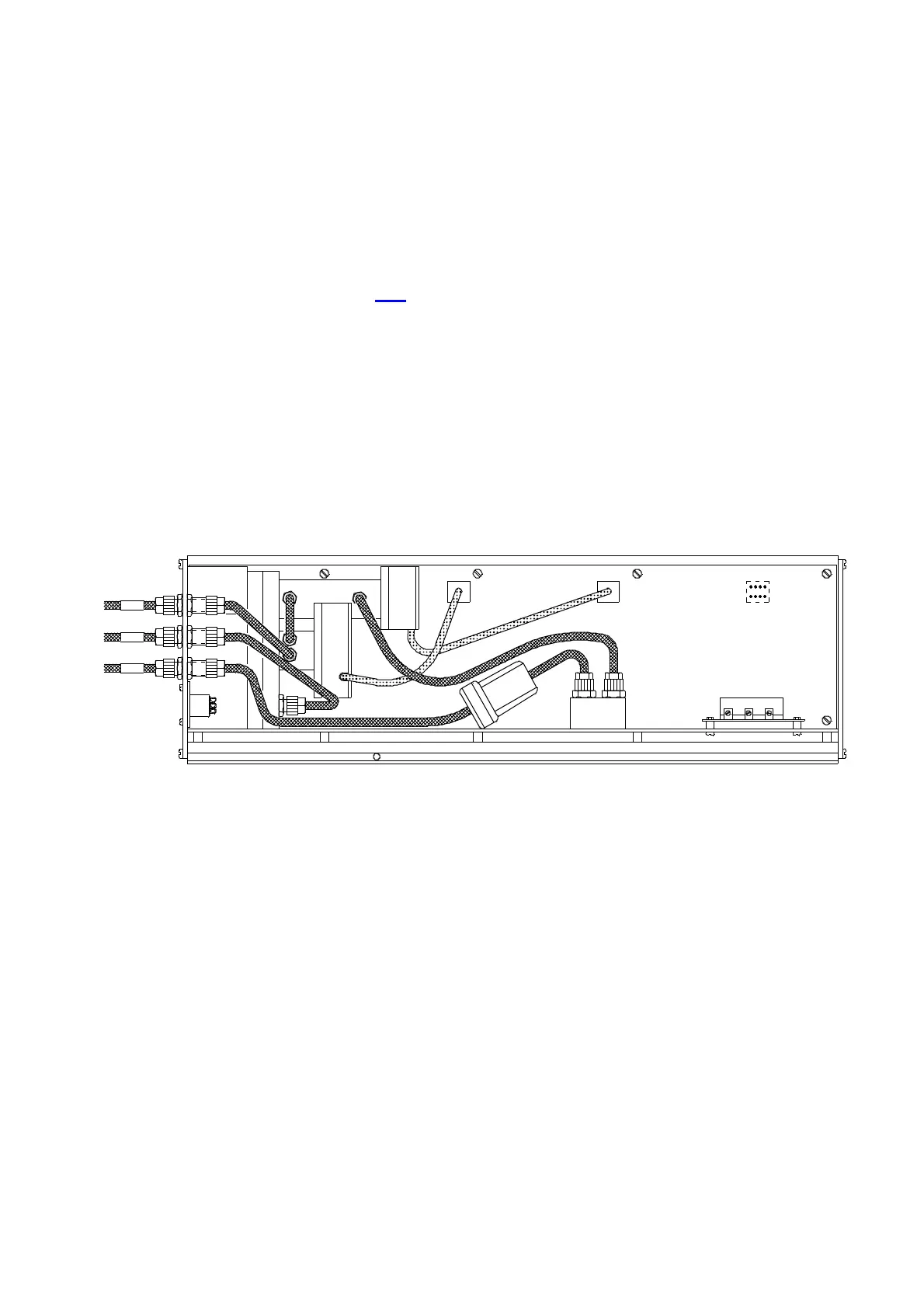
When the test signal fails on test point 1, this can be due to the 8-pin connector
( 10 / 11 ) that connects the pre-amplifier to the IR21 board not being correctly
connected.
Remove, turn 180°, and replace the 8-pin-connector and measure again.
1 black marked tube connection
2 yellow marked tube connection
3 red marked tube connection
When reinstalling the infrared cell into the analyser, you must pay attention to the
color markings of the tubes and their connections.
CO
1
2
3
CO
2
2
sw
ge
2 -3 -4
1110
rt