2002 by ELTRA GmbH Germany – January 2002 – Service Manual OH 900 / ON 900 / ONH 2000
2.18-2
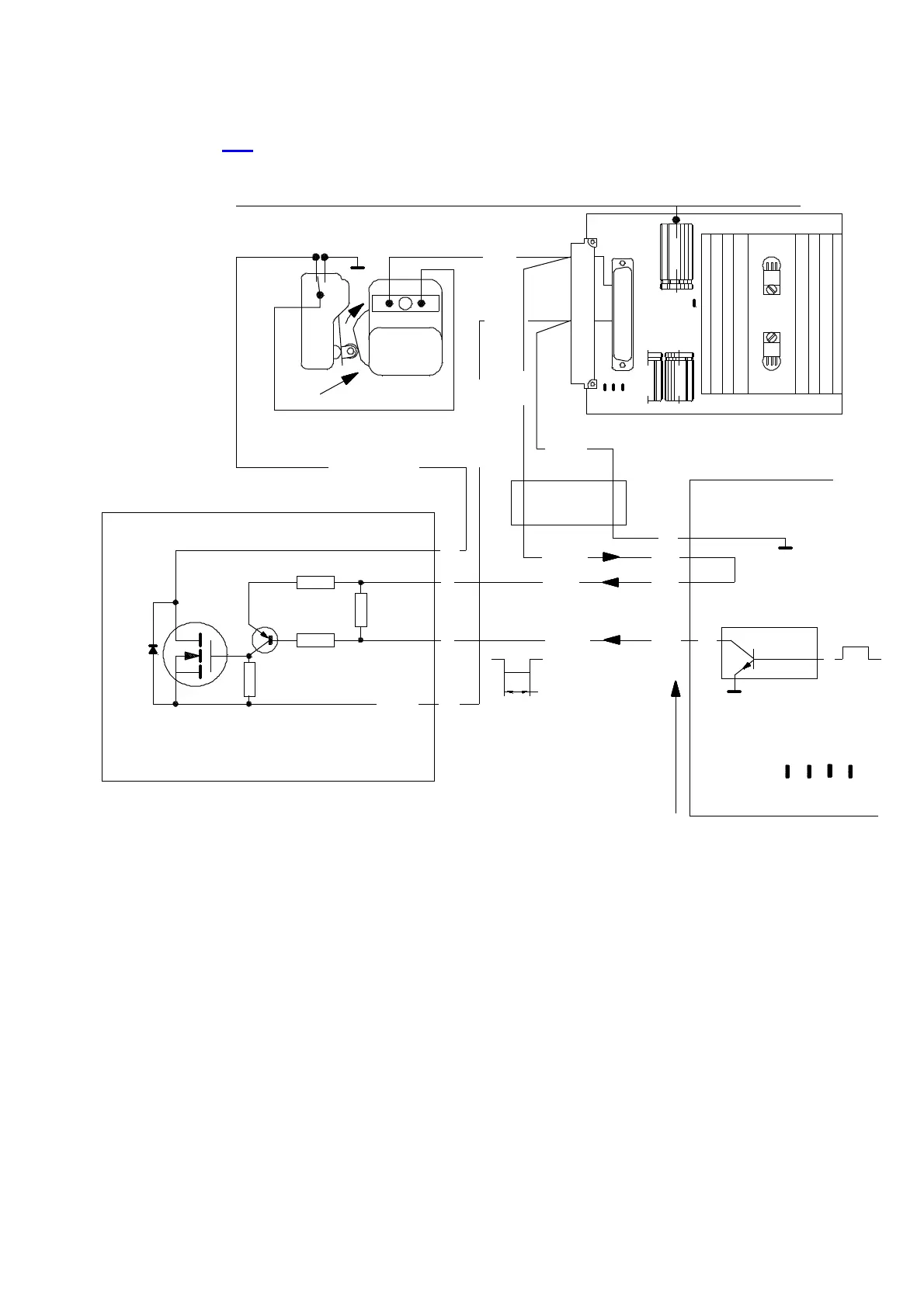
The detailed circuit is as follows :
See also 4. 2 wiring diagrams 32165 resp. 32167 and 32140.
+
-
10k
18k
BC327
IRF820
G
R38
R45
T3
T4
D
S
10k
100k
4007
D12
+1 5V -15 V
GND
NK31 16100
6
30
ECCE NTER
12
139
1
SAMPLE DROP
MOTOR
green/pink
R47
ON21
G ND
4
15
16b
20a
18a
IC4 on MP 68000
IC3 on 68k
DRIVER
sw
rt
GND
GND
+24VDC
ELECTRONIC RACK
brown/grey
brown
red
green
1a
red
withe
red
96 PIN PLUG
2 seconds
+24VDC
2
1
10
11
PW13
R46
POWER SUPPLY
GND
SWITCH
GND
+5 V
+1 5V
black
MOTOR
- 1 5 V
T3 and T4 with the connected components
are a separate circuit on the PW 13
1-14-3
GND is also the minus of the big capacitor (two of then on the old NK3)
2 2 ac
2 4 ac
+2 4V
 Loading...


