EM Test CWS500 N2
User manual V 3.00 22 / 38
Calibration Setup EM TEST and IEC 61000-4-6
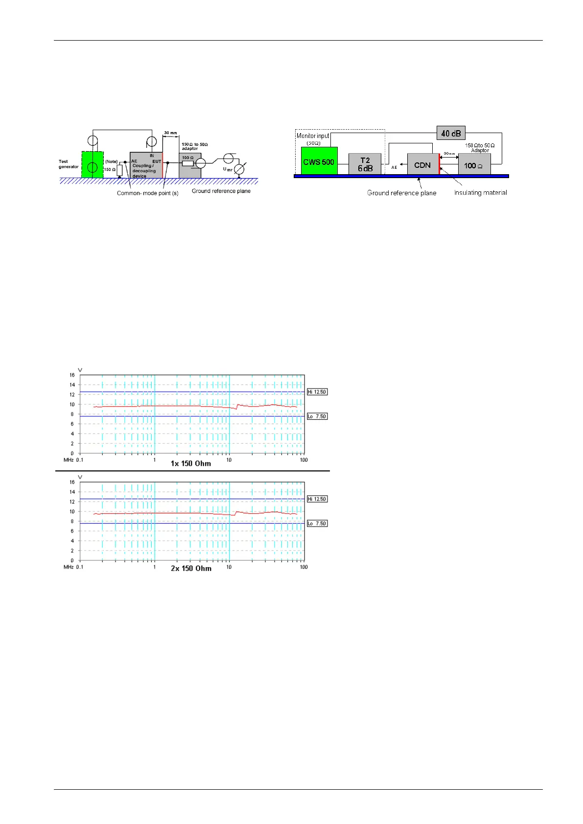
The setup for calibration according to IEC 61000-4-6 is shown in the figure 5.7. below. EM Test has carefully
tested the calibration setup and propose to eliminate the 150
terminating resistor on the AE port for CDN
calibration. ( Fig 5.8)
Fig 5.7 : Calibration Setup per IEC 61000-4-6
Fig 5.8 : Calibration Setup EM Test method
Reason for the EM Test calibration test setup:
- The AE port must only be applied to unshielded cables (shielded cables have their shielding connected to the
ground reference plane of the AE port).
- The uncoupling inductance according to the standard is >280
H. The EM Test CDN has a higher inductance
(CDN M3 typical >500
H). Therefore, the calibration error at 150kHz is max 10% and will be reduced by
increasing the frequency. (Error at 400kHz approx.5%).
- The tolerance of the applied signal according to IEC 61000-4-6 is
25%. The figure below shows two CDN M3
10V measurements with different calibration methods. The results are within the
25% limit and the result is
very similar.
- The influence of the internal synthesizer attenuator is responsible for the non-linear result of the calibration
test.
EM Test Calibration Setup
EUT port : 1x 150:
R100 ( 100 )
power meter ( 50 )
AE port : open circuit
IEC 61000-4-6 Setup
EUT port : 1x 150:
R100 ( 100 )
power meter ( 50 )
AE port : 1x 150:
R100 ( 100 )
terminating ( 50 )
Fig 5.9 : Difference between the calibration methods
However, for a calibration according to the standard it is necessary to add the additional calibration acessories
for the AE port termination :
150 to 100 adapter : R-100
50 termination resistor : T-50