Do you have a question about the EM TEST CWS 500D and is the answer not in the manual?
Before using the CWS 500 D read the following manuals carefully.
Details on rear panel connections for different models.
Illustrates typical test configurations for BCI applications.
Lists and describes the main components and accessories.
Details clamps used for automotive EMC testing.
Explains the use of Coupling/Decoupling Networks for IEC standards.
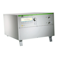
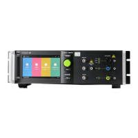
Identifies and describes the front panel controls and indicators.
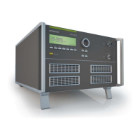
Details the rear panel connectors and ports for the 400MHz model.
Details the rear panel connectors and ports for the 1GHz model.
Describes the menu control system and function keys.
Provides a fast method for function checks and verification.
Guides on using Quickstart for calibration with external signal generators.
Shows information displayed during remote operation via ICD software.
Explains different modulation types like AM and PM.
Accesses service functions like addresses, setup, and checks.
Displays contact information for EM TEST and its sales partners.
Configures language, display, interfaces, and timers.
Allows selection between internal and external amplifiers.
Crucial safety guidelines for RF disturbance testing and equipment handling.
Procedure to verify the performance and accuracy of the generator.
Checks the built-in 3-channel powermeter for correct function.
Verifies the correct operation of the built-in amplifier switch for the 1GHz model.
Detailed procedures for setting up and performing calibrations.
Specific calibration setup for BCI applications according to various standards.
Calibration method proposed by EM TEST for IEC 61000-4-6.
Setup for calibration procedures involving Coupling/Decoupling Networks (CDN).
Setup for calibration procedures using an EM Clamp.
Describes the behavior of the Fail 1 and Fail 2 inputs for test control.
Explains the processing unit and driver electronics for the HF section.
Details the signal generator and its modulators.
Describes the class A amplifier and its specifications.
Explains the function and use of the optional 3dB attenuator.
Details the external CDN components used for coupling disturbance signals.
Important information for creating a correct test setup using CDNs.
Setup for tests involving DUT current monitoring with clamps.
Specifies test severity levels and frequency ranges for ISO and IEC standards.
Basic information on the maintenance-free nature and cooling of the generator.
Covers factory calibration, verification guidelines, and accessory calibration.
Details the factory checking, calibration process, and certification.
Provides advice on setting calibration intervals based on usage and QA policy.
Specifies calibration for passive accessories.
Guidance on performing periodic in-house checks.
Lists the standard items included with the CWS 500D.
Details optional items and accessories available for the CWS 500D.
Visual representation of the CWS 500D's internal structure and signal flow.
Formal declaration of the product's compliance with relevant EC directives and standards.
| Brand | EM TEST |
|---|---|
| Model | CWS 500D |
| Category | Laboratory Equipment |
| Language | English |