EM Test CWS500 D
User manual V 1.07 4 / 34
2.3. Part Identifications and Functions
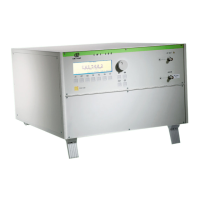
Continuous Wave Simulator CWS 500D 400MHz
CWS 500D 1GHz
Fig 2.4
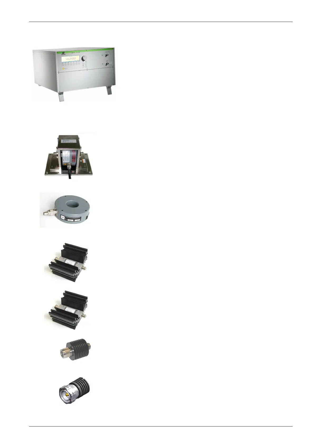
2.3.1. Clamp Applications for Automotive standards
Fig 2.5
Bulk Current Injection Clamp BCI type ( selection of clamps)
F-130-A1 10kHz – 400MHz
F-120- 6A 10kHz – 400MHz
FCC-BCICF-1 Calibration Fixture for BCI clamp (jig)
F-140A 100kHz - 1000 MHz
FCC-BCICF-2 Calibration Fixture for BCI clamp (jig)
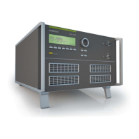
Fig 2.6
Current Monitor Probe
F-33-2 1kHz – 250MHz
F- 55 10kHz – 500MHz
F- 65 100kHz - 1GHz
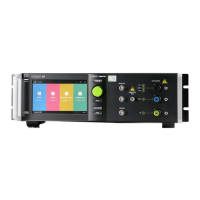
Fig 2.7
Attenuator 3dB optional
Type ATT3/100
3dB 100W
Fig 2.8
Attenuator 20dB ( for DO and MIL application )
Type ATT20/100
20dB 100W
Fig 2.9
Attenuator 20dB
20dB 15W
Fig 2.10
Terminating resistor 50 Ohm optional
50 Ω 6W