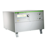
EM Test CWS500 D
User manual V 1.07 6 / 34
3. Operating Functions
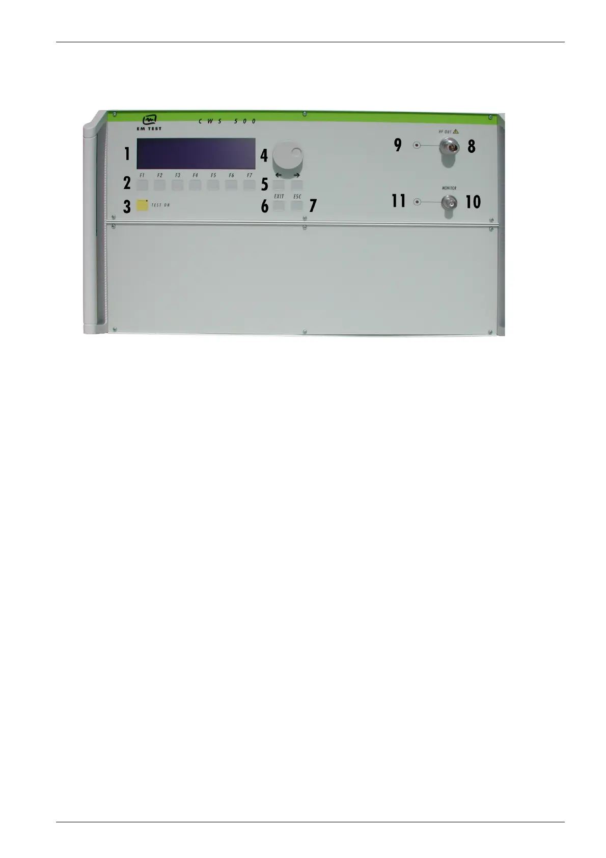
3.1. Front View
Fig 3.1
1. Display
2. Function keys "F1..F7"
3. "Test On"
4. Knob (Inc / Dec)
5. Cursor keys "←" and "→"
6. Exit
7. Escape
8. RF Output
9. LED RF Output Monitor
10. Current Probe Input (Monitor)
11 LED Current Probe Input
1Display
All functions and parameters are displayed (8 lines with max. 40 characters).
2 Function Keys "F1 .. F7"
Parameters and functions displayed in the lowest line and functions displayed with ” F “, can be selected
with the related function key.
3 Test On
By pressing the key "TEST ON", the RF signal will be released and the test procedure can be started.
4 Knob (Inc / Dec)
This knob increments or decrements parameters with a numeric value or selects parameters from a list.
5Cursor Key
Parameters and functions can be changed during the test. The selection of these parameters is done with
the cursor, moving it to the left or to the right.
6 EXIT
The EXIT button resets the firmware to the main menu. This is only possible, if no test routine is running.
7 ESC
The ESC button returns back to the previous level in the menu.
8 RF-Output
At this output the RF power is available. The 3dB-attenuator is connected, if available, via coaxial cable.
For conducted tests together with CDN’s, EM clamps or current injection clamps, it may be suggested to
load the simulator with a matched 50 ohm load. In case the above mentioned coupling device may not
represent such matched load, then it is recommended to add a 3dB attenuator in between.
9 LED RF Output Monitor
When the RF output is active this LED on the front panel is illuminated to indicate that a test signal is
generated.
10 Current Probe Input
For tests with a current injection clamp where the EUT current has to be measured and/or monitored, the
current probe can be connected to this input.
ATTENTION: Do not connect the RF output directly to this input otherwise it will be damaged.
11 LED Current Probe Input