EM Test CWS500 D
User manual V 1.07 7 / 34
When current monitoring is active this LED on the front panel is illuminated.
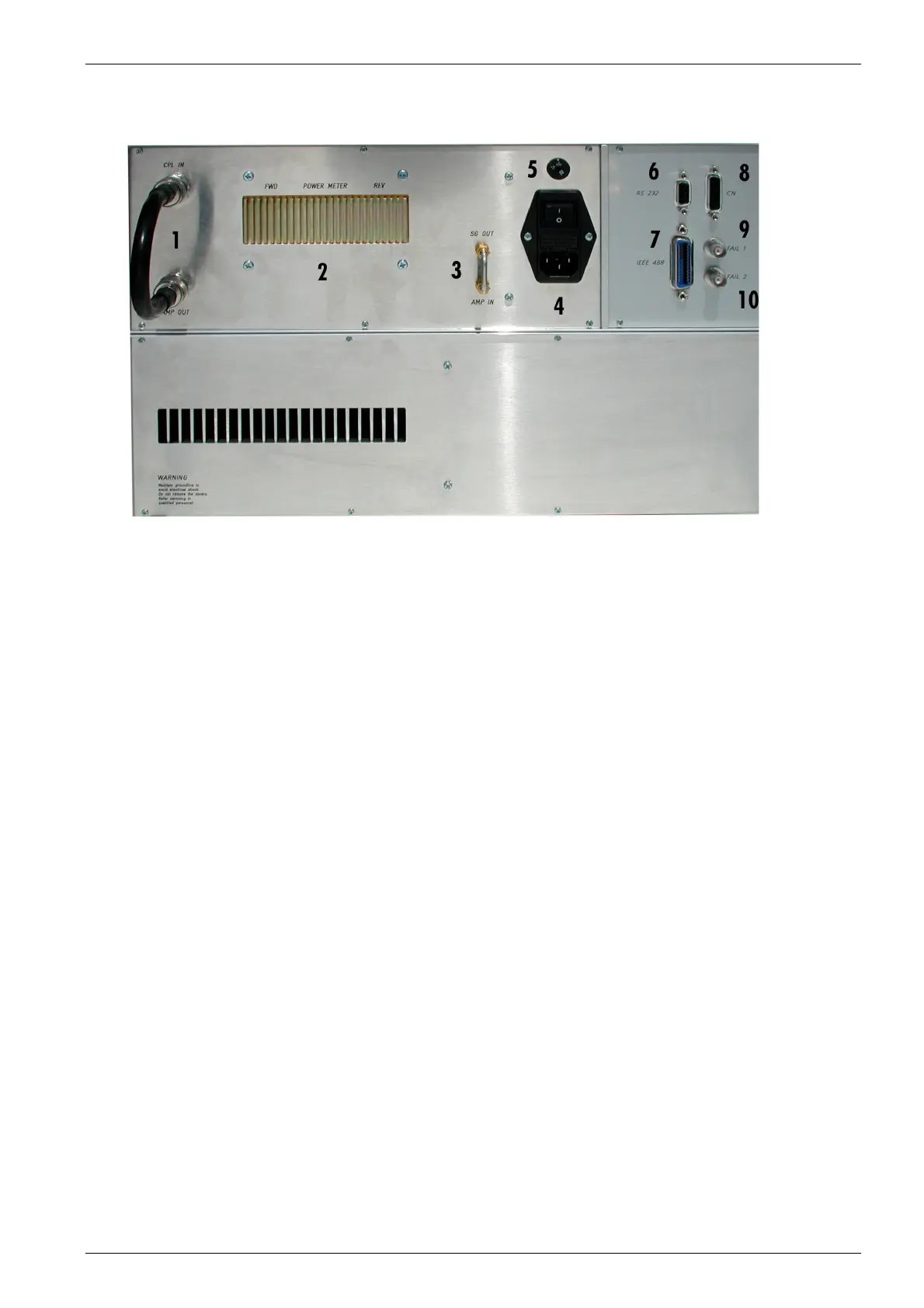
3.2. Rear view CWS 500D 400MHz model
Fig 3.2
1 Connection Amplifier OUT to Coupling IN
2 Bi-directional coupler
3 Connection Signal Generator to Amplifier
4 Power On Switch
5 Power selector 115V – 230V
6 Serial Interface RS 232
7 IEEE Interface
8 Remote Control Connector
9 Fail 1 Detection "Stop"
10 Fail 2 Detection "Pause"
1 Connection Amplifier OUT to Coupling IN
This connection link is between the amplifier and the power measurement device to the RF Output at the
front side. The user has the possibility to connect the amplifier to another device like a TEM cell.
2 Bi- directional coupler
3 Amp In / SG Out
The internal amplifier can be controlled by an external signal generator. For this operation, the short circuit
link must be disconnected. The external signal generator must be plugged into the connector “Amp In”.
4 Power On Switch
The switch and the main fuses are part of this box. (230V / 3.15AT or 115V / 6.3AT)
5 Power selector
Input power selector for input voltage 115V – 230V.
6 Serial Interface
RS 232 interface with 9-pin connector.
7 Parallel Interface IEEE
IEEE 488 interface with IEEE connector.
8 Remote Control Connector
not used.
9 Fail Detection FAIL 1 (TEST STOP)
The BNC input FAIL 1 can be used for failure detection on the EUT. If the input is set to ground (chassis),
the CWS 500D generator will be stopped and finish the test routine. It is not possible to continue the test.
A complete restart of the routine will be necessary. The message "FAIL 1" is indicated in the ICD software.
10 Fail Detection FAIL 2
The BNC input FAIL 2 can be used for failure detection on the EUT. If the input is set to ground (chassis),
the failure will be detected and the test continues normally. After a FAIL 2 events the test routine will stop
and the message ”FAIL 2“ will appear in the host screen ( ICD software).