EM Test CWS500 D
User manual V 1.07 8 / 34
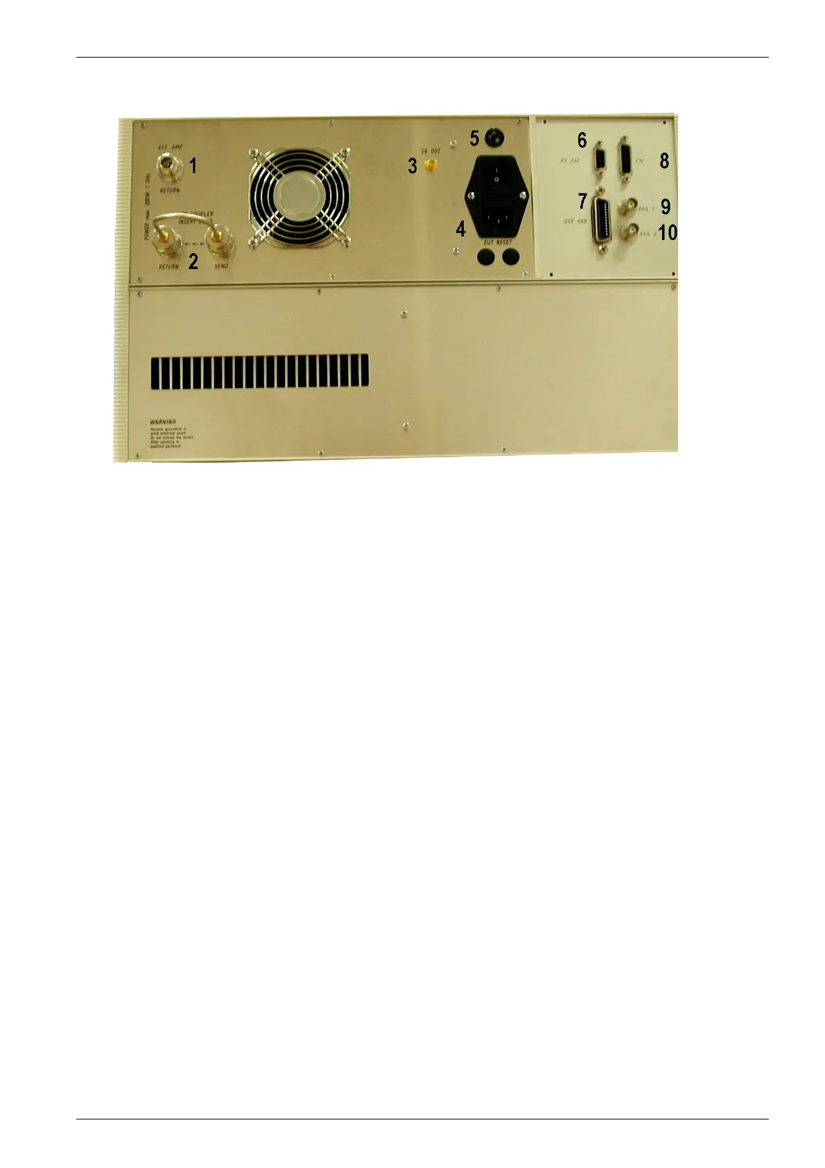
3.3. Rear view CWS 500D 1GHz model
Fig 3.3
1 Connection Ext. Amplifier RETURN
2 Pre coupler insert loop
3 SG out
4 Power On Switch
5 Power selector 115V – 230V
6 Serial Interface RS 232
7 IEEE Interface
8 Remote Control Connector
9 Fail 1 Detection "Stop"
10 Fail 2 Detection "Pause"
1 Connector External Amplifier (EXT AMP Return )
Input signal from an external amplifier. ( max. power 200W)
2 Pre Coupler insert loop
Output and return connection for the external device like a filter or TEM cell
3 SG Out
Output to an external amplifier for control an amplifier >100W .
4 Power On Switch
The switch and the main fuses are part of this box. (230V / 3.15AT or 115V / 6.3AT)
5 Power selector
Input power selector for input voltage 115V – 230V.
6 Serial Interface
RS 232 interface with 9-pin connector.
7 Parallel Interface IEEE
IEEE 488 interface with IEEE connector.
8 Remote Control Connector
not used.
9 Fail Detection FAIL 1 (TEST STOP)
The BNC input FAIL 1 can be used for failure detection on the EUT. If the input is set to ground (chassis),
the CWS 500D generator will be stopped and finish the test routine. It is not possible to continue the test.
A complete restart of the routine will be necessary. The message "FAIL 1" is indicated in the ICD software.
10 Fail Detection FAIL 2
The BNC input FAIL 2 can be used for failure detection on the EUT. If the input is set to ground (chassis),
the failure will be detected and the test continues normally. After a FAIL 2 events the test routine will stop
and the message ”FAIL 2“ will appear in the host screen ( ICD software).