EM Test CWS500 N2
User manual V 3.00 24 / 38
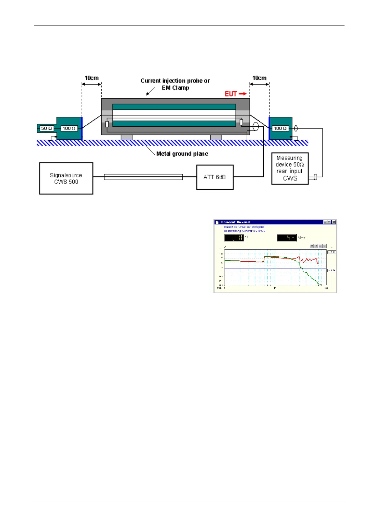
Calibration Setup with EM Clamp
The calibration with an EM Clamp is similar to the CDN calibration.
Fig 5.14 : Calibration setup with EM Clamp
Make sure to connect the EM clamp correctly in the test and
calibration setup. The EUT port must be on the measuring
device side, or calibration in the higher frequency range will be
wrong.
Correct setup : Red line with correct EM Clamp direction
Wrong setup : Green line ( reduced signal at high frequency)
Fig 5.15 : Measuring result with correct and wrong EM Clamp direction
Failure Input
Fail 1: A short circuit at the Fail 1 input will stop the test procedure. It is not possible to continue this test.
Fail 2: A short circuit at the Fail 2 input will store the actual test data. The test procedure will continue normally
after Fail 2 is released. The display indicates the number of Fail 2 events.
After the first Fail 2, the following events on the same test level are ignored (for the actual selected dwell
time).
After 10 Fail 2 events, the test procedure will stop automatically.