EM Test CWS500 N2
User manual V 3.00 27 / 38
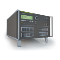
6dB Attenuator
The 6dB attenuator is connected directly to the RF-output of the
CWS 500N1. The attenuator has to be used together with the
CWS 500N1 and matches the output to a 50 system. The
attenuator must be connected as close as possible to the
coupling/uncoupling network (CDN, EM clamp or current injection
clamp), using a 50cm (20 inch) coaxial cable.
Fig 8.5 : ATT 6/75
The attenuator is symmetrical designed. It doesn’t matter where is the input/output.
The attenuator is required in the actual standard. However, the included amplifier will work correctly with any
load. Although the CWS 500N1 can also be used correctly without the 6dB-attenuator, all functions of the
CWS 500N1 and the ICD.control software is designed to be used with the 6dB-attenuator.
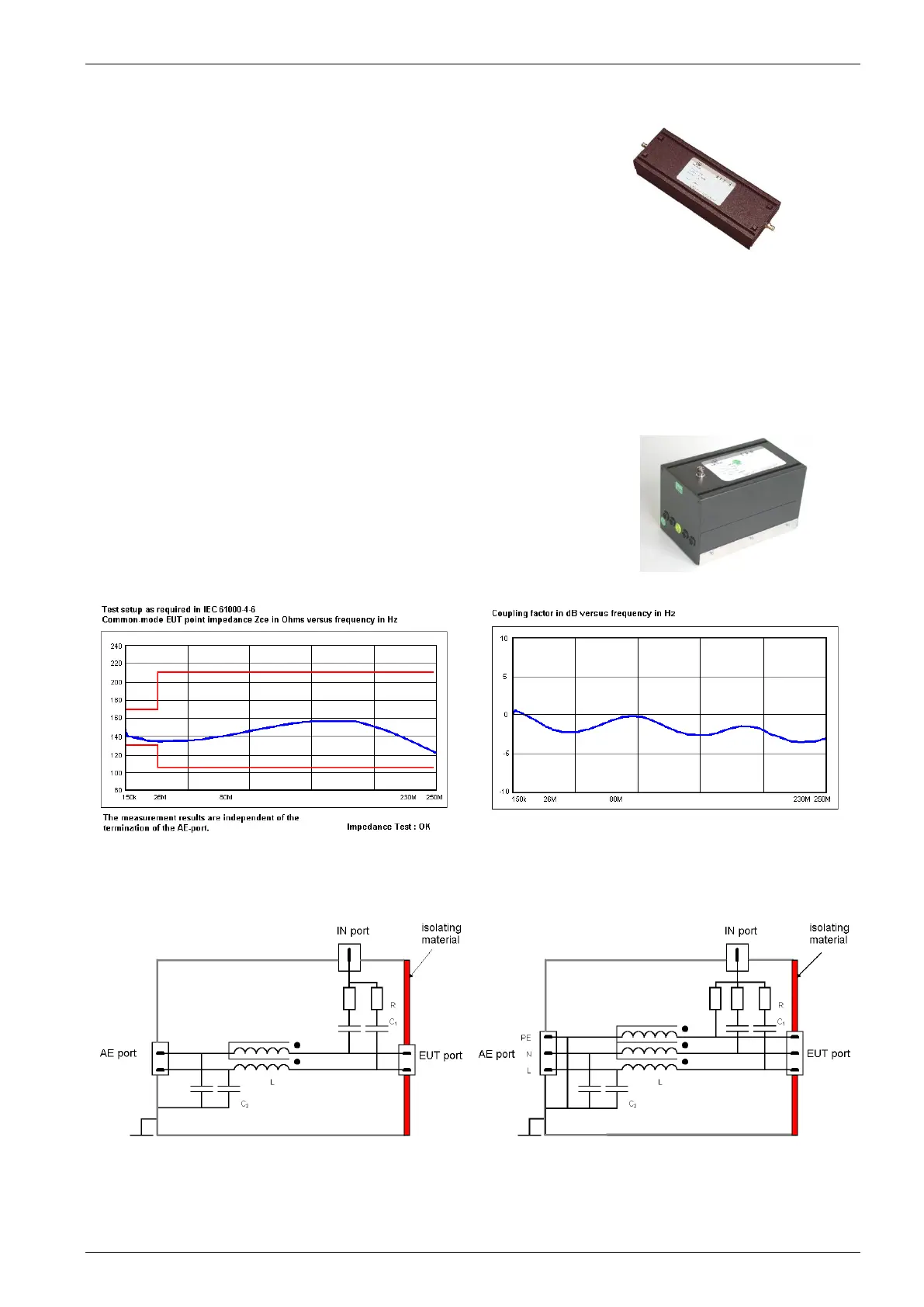
CDN Coupling/ Decoupling Network
The CDN’s are connected externally to the output of the simulator or the
6dB-attenuator. The coupling network is used to couple the disturbance
signal to the lines of the equipment under test. The coupling is
accomplished with capacitors or resistors having a sufficient bandwidth
according to IEC 61000-4-6.
The components, such as the common mode impedance and the
coupling factor are specified within the standard. Fig 6.5 : CDN M5
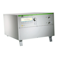
Fig 6.6 : Typical Impedance Zce of a CDN
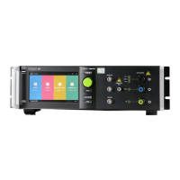
Fig 6.7 : Typical Coupling factor of a CDN
Examples of a single shielded line (S1) and a 3-line power supply (M3) are shown below.