EM Test CWS500 N2
User manual V 3.00 8 / 38
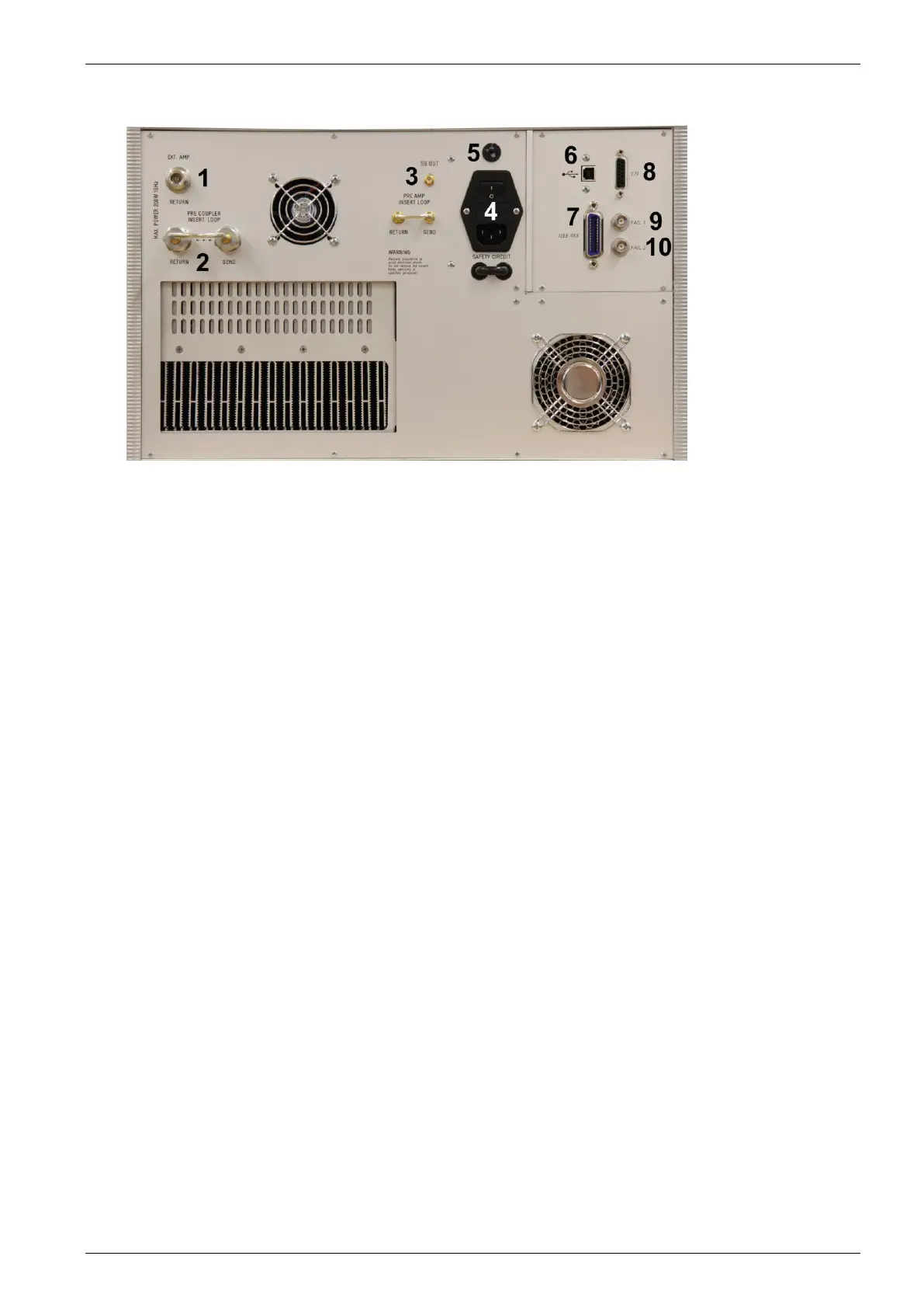
Rear view CWS 500N2
1 Connection Ext. Amplifier RETURN
2 Pre coupler insert loop
3 SG out
4 Power On Switch
5 Power selector 115V – 230V
6 USB Interface
7 IEEE Interface
8 Remote Control Connector
9 Fail 1 Detection "Stop"
10 Fail 2 Detection "Pause"
11 Pre Amp Insert Loop
1 Connector External Amplifier (EXT AMP Return )
Input signal from an external amplifier. ( max. power 200W)
2 Pre Coupler insert loop
Output and return connection for the external device like a filter or TEM cell
3 SG Out
Output to an external amplifier for control an amplifier >100W .
4 Power On Switch
The switch and the main fuses are part of this box. (230V / 3.15AT or 115V / 6.3AT)
5 Power selector
Input power selector for input voltage 115V – 230V.
6 USB interface
USB interface “USB B” connector. For datatransfer a USB interface is available. The internal RS 232
interface is converted to USB standard. Therefore the user must set the same Baudrate in the device and
control software.
Using the USB interface the user can have emc problems during burst tests Our experiences says, that
usually the computer USB port is disturbed by interference’s. Therefore a high quality USB cable ( USB 2.0
standard) must be used.
7 Parallel Interface IEEE
IEEE 488 interface with IEEE connector.
8 Remote Control Connector
not used.
9 Fail Detection FAIL 1 (TEST STOP)
The BNC input FAIL 1 can be used for failure detection on the EUT. If the input is set to ground (chassis),
the CWS 500N2 generator will be stopped and finish the test routine. It is not possible to continue the test.
A complete restart of the routine will be necessary. The message "FAIL 1" is indicated in the icd.control
software.